Supercharge Your Innovation With Domain-Expert AI Agents!

A high-stability timing signal generation method and device

A technology for generating devices and timing signals, which is applied in the direction of single output arrangement, etc., can solve the problems of difficult compensation, limited precision, and difficulty in obtaining accurate compensation, so as to avoid inconsistent lengths of space traces, low sensitivity, and reduce nonlinearity Effect

Active Publication Date: 2021-08-10
HUAZHONG UNIV OF SCI & TECH
View PDF6 Cites 0 Cited by
  • Summary
  • Abstract
  • Description
  • Claims
  • Application Information

AI Technical Summary

Problems solved by technology

[0004] At present, the timing signal generator based on FPGA mainly adopts the digital time conversion technology (DTC) based on the carry delay chain. Since the delay value of the delay unit of the carry chain is greatly affected by environmental factors (especially temperature), there is nonlinearity. Larger errors lead to limited accuracy, and additional compensation design and pre-correction are required; in addition, when the general carry chain is used as a DTC for delay or external trigger except for shaking, because its structure has a large spatial span, its output taps to The trace length of a specific final output port is difficult to control to be consistent, causing additional uncontrollable delay differences, and changes with design changes, it is difficult to obtain accurate compensation, resulting in a decrease in delay accuracy; patent CN106656121A discloses a A method that uses a hardware structure (capacitor discharge slope comparison) for delay shake compensation processing is also inaccurate due to the inherent error of the hardware itself and requires an additional compensation structure. The wiring fluctuation of external hardware becomes the source of timing error, and the accuracy of external trigger mode can only reach 0.8ns
These problems lead to the above-mentioned timing signal generation technology having the shortcomings of low delay accuracy, difficult compensation, or insufficient compensation accuracy, and it is difficult to align with the real trigger signal and obtain a timing pulse based on the actual trigger.

Method used


Image

  • A high-stability timing signal generation method and device
  • A high-stability timing signal generation method and device
  • A high-stability timing signal generation method and device

Examples


Embodiment Construction

[0031] In order to make the objectives, technical solutions and advantages of the present invention, the present invention will be described in further detail below with reference to the accompanying drawings and examples. It should be understood that the specific embodiments described herein are merely intended to illustrate the invention and are not intended to limit the invention.

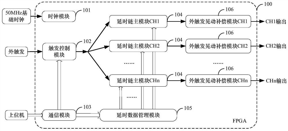
[0032] High stability of the present invention provides a timing signal generating means comprises: a clock module 101, trigger control module 102, a communication module 103, a main chain of n-channel delay module 104, data management module 105 and the delay of n external trigger shake compensation module 106; 101 output clock module connected to all other modules, to provide a stable and reliable clock source; trigger control module 102 is connected with the communication module 103 receives the trigger mode setting data from the host computer, while the n-channel extension when the chain 104 are...


PUM


Abstract

The invention discloses a high-stability sequence signal generation method and device. The method includes: selecting a trigger source according to a control signal, setting a delay length and a pulse duration; using a counter to delay and store the number of delay cycles in the control data It is set and used as the first level, using the integrated feedback delay chain module and taking the half cycle of the clock source as the total length of the m-level delay of the whole chain to realize the construction of the delay path; when the trigger signal comes, it will be generated when the trigger is captured The reference signal, the main delay path starts a two-stage delay accordingly; the external trigger TDC chain measures the time difference between the trigger signal and the reference signal, and obtains the integrated feedback delay chain stages to be compensated according to the time difference; when the main delay ends, The pulse edge is sent into the compensation delay, and the signal with the internal reference as the reference delay is converted into a fixed delay signal with the original trigger as the reference, and the pulse shaking caused by the capture is eliminated through the integrated feedback delay chain to output high stability timing signal.

Description

Technical field [0001] The present invention relates to the field of timing control, and more particularly to a timing signal generating method and apparatus for high stability. Background technique [0002] In the experimental device of nuclear magnetic resonance, quantum calculation, ultrasonic, medical test, any timing signal generator (ATG) has an important role in coordination and synchronization control of the various parts of the device system. By generating a timing trigger pulse different from the delay, the device can accurately control each module in the system, the startup time of each action, coordinates the operation of each component in the system, thereby triggering or external signal triggering inside instructions In the case, the timing operation is performed correctly according to the set order. [0003] The basic requirement of the timing signal generating device is that the triggering order of each channel pulse is even more programmable control, and the dela...

Claims


Application Information

Patent Timeline
Patent Type & Authority Patents(China)
IPC IPC(8): H03K5/13
CPCH03K5/13
Inventor 韩小涛邱文捷谢剑峰刘沁莹
Owner HUAZHONG UNIV OF SCI & TECH
Features
  • R&D
  • Intellectual Property
  • Life Sciences
  • Materials
  • Tech Scout
  • Unparalleled Data Quality
  • Higher Quality Content
  • 60% Fewer Hallucinations
Learn More