Check patentability & draft patents in minutes with Patsnap Eureka AI!

Piezoresistive pressure sensing circuit

A sensing circuit, piezoresistive technology, applied in the direction of measuring fluid pressure, sensors, measuring devices, etc., can solve the problems of large temperature difference, large dispersion, inaccurate temperature, etc., to achieve accurate blood pressure values ​​and improve accuracy. Effect

Pending Publication Date: 2021-03-05
SHENZHEN INSIGHT MED CO LTD
View PDF0 Cites 0 Cited by
  • Summary
  • Abstract
  • Description
  • Claims
  • Application Information

AI Technical Summary

Problems solved by technology

[0003] There are two main problems in the existing method of calculating the temperature of the half-bridge piezoresistive pressure sensor based on ADC single-ended sampling. The first is that the method directly uses the half-bridge resistance output by the ADC to calculate the temperature, and there is filtering or other problems in the circuit. In the case of a circuit, the resistance output by the ADC is not equal to the real resistance value of the sensor half-bridge, which will lead to inaccurate calculated temperature; the second is that the calculation process is too dependent on the correlation coefficient given by the sensor manufacturer (such as the influence of temperature on resistance Coefficient K T , The influence coefficient of pressure on resistance K P , Temperature influence coefficient K on sensitivity S ), the dispersion of these coefficients is large, which will lead to large differences in the temperature calculated by different sensors, and poor consistency of temperature measurement, which will lead to inaccurate measured pressure values

Method used


Image

  • Piezoresistive pressure sensing circuit
  • Piezoresistive pressure sensing circuit
  • Piezoresistive pressure sensing circuit

Examples


no. 1 Embodiment approach

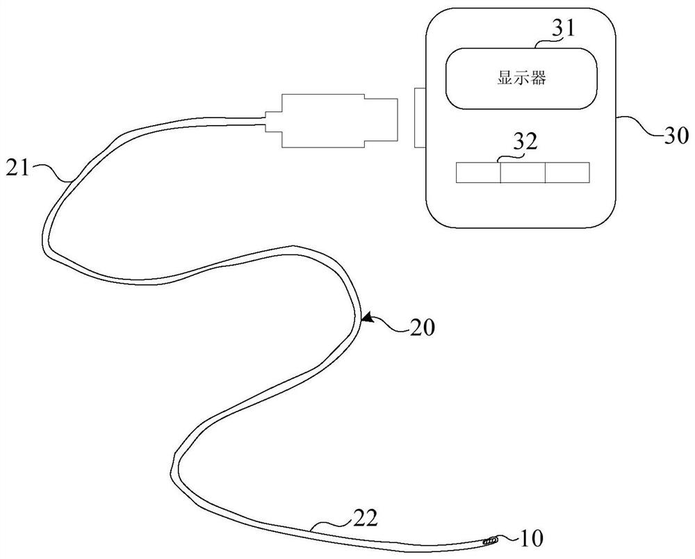
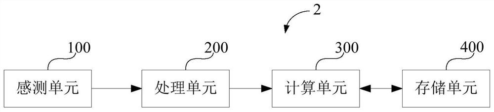
[0028]figure 1 It is a schematic diagram showing the intravascular pressure measurement catheter 1 according to the first embodiment of the present disclosure; figure 2 is a schematic block diagram showing the piezoresistive pressure sensing circuit according to the first embodiment of the present disclosure.

[0029] refer to figure 1 and figure 2 , the piezoresistive pressure sensing circuit involved in this disclosure can be applied in such as figure 1 Intravascular pressure measurement catheter 1 is shown. The intravascular pressure measurement catheter 1 involved in this embodiment may include a sensing unit 10 , a flexible catheter 20 and a host 30 .

[0030] In this embodiment, the sensing unit 10 can be used to sense the blood pressure value at a predetermined position in the blood vessel. The flexible catheter 20 may have a proximal portion 21 connected to the host 30 and a distal portion 22 connected to the proximal portion (see figure 1 ). Additionally, the ...

no. 2 Embodiment approach

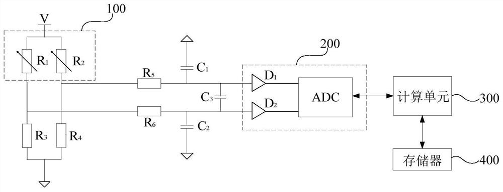
[0083] Figure 6 It is a schematic circuit diagram showing an example of a specific configuration of the piezoresistive pressure sensing circuit 2 according to the second embodiment of the present disclosure; Figure 7 It is a schematic circuit diagram showing another example of the specific configuration of the piezoresistive pressure sensing circuit 2 according to the second embodiment of the present disclosure.

[0084] The main difference between this embodiment and the first embodiment is that the position of the sensing unit 100 can be flexibly set in the position of the third resistor R 3 and the fourth resistor R 4 the other side of the (eg Figure 6 and Figure 7 Shown by the third resistor R 3 and the fourth resistor R 4 the lower side of the ). Hereinafter, a detailed description will be mainly aimed at the above-mentioned different points.

[0085] In this embodiment, if Figure 6 As shown, the position of the first variable resistor R is different from tha...


PUM


Abstract

The invention discloses a piezoresistive pressure sensing circuit which is applied to a blood vessel internal pressure measuring catheter. The piezoresistive pressure sensing circuit comprises a sensing unit, a processing unit and a calculating unit, wherein the sensing unit is used for detecting blood pressure in a blood vessel and outputting a blood pressure signal, and the sensing unit comprises a first pressure sensing component with a first variable resistance element and a second pressure sensing component with a second variable resistance element; the processing unit is connected with the sensing unit, receives the measured blood pressure signal measured by the sensing unit and processes the measured blood pressure signal; and the calculating unit receives the measured blood pressure signal processed by the processing unit and compensation parameters and a function relation from a storage unit, and calculates a real blood pressure value based on the measured blood pressure signal, the compensation parameters and the function relation. According to the piezoresistive pressure sensing circuit, under the condition, the calculating unit can obtain a correct blood pressure valuebased on the compensation parameters and the function relation during calculation, and the accuracy of measuring the blood pressure value in the blood vessel can be further improved.

Description

technical field [0001] The present disclosure generally contemplates a piezoresistive pressure sensing circuit. Background technique [0002] Due to the limitation of the sensor processing technology, the pressure measurement results of some semi-Wheatstone bridge piezoresistive pressure sensors are greatly affected by the temperature, and the sensor temperature needs to be used to compensate the pressure measurement results. In some cases, the temperature of the sensor can be measured by a special temperature measurement component, but this method will have a great impact on the structure and volume of the sensor. Another way is through the change of the variable resistance of the two half-bridges of the sensor The temperature of the sensor is calculated according to the situation, and this method can be realized based on a general-purpose half-bridge piezoresistive pressure sensor without additional temperature measurement circuits or structures. [0003] There are two ma...

Claims


Application Information

Patent Timeline
IPC IPC(8): A61B5/0215A61B5/00G01L19/04
CPCA61B5/0215A61B5/6852A61B5/72A61B5/7203G01L19/04A61B2560/0252
Inventor 王武涛熊双涛
Owner SHENZHEN INSIGHT MED CO LTD
Features
  • R&D
  • Intellectual Property
  • Life Sciences
  • Materials
  • Tech Scout
  • Unparalleled Data Quality
  • Higher Quality Content
  • 60% Fewer Hallucinations
Learn More