Circuit device and method for improving consistency of thermal printing concentration

A technology of thermal printing and thermal print head, which is applied in printing and other directions

Active Publication Date: 2021-03-05
北京百舸飞驰科技有限公司
View PDF12 Cites 2 Cited by
  • Summary
  • Abstract
  • Description
  • Claims
  • Application Information

AI Technical Summary

Problems solved by technology

[0005] The technical problem to be solved by the present invention is to provide a circuit device and method for improving...

Method used


Image

  • Circuit device and method for improving consistency of thermal printing concentration
  • Circuit device and method for improving consistency of thermal printing concentration
  • Circuit device and method for improving consistency of thermal printing concentration

Examples


Embodiment 1

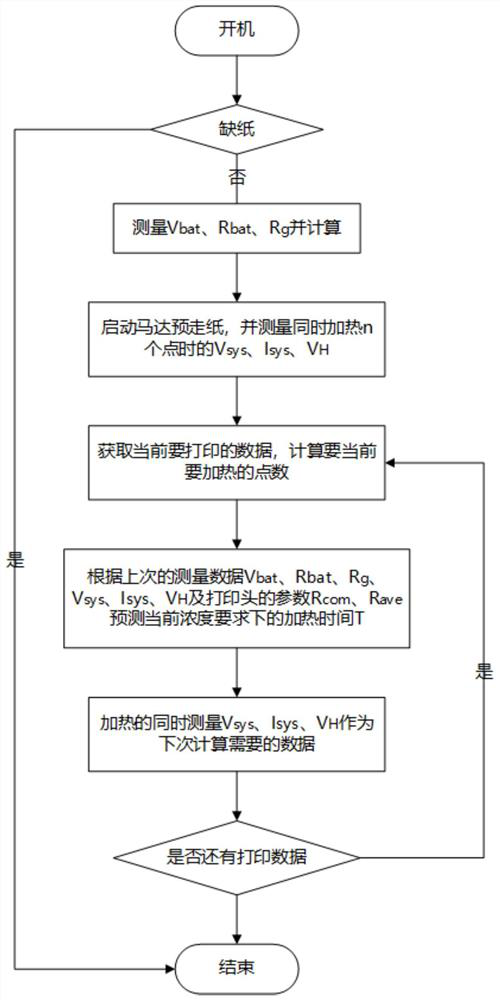
[0076] First aspect, such as Figure 1-3 As shown, the present invention provides a technical solution: the present invention provides a circuit method for improving the density consistency of thermal printing, which includes the following steps: after the thermal printer is turned on, first measure and calculate the battery voltage V bat , battery internal resistance R bat , the on-resistance R of the thermal print head power switch g :

[0077] a. Check whether there is paper, otherwise exit;

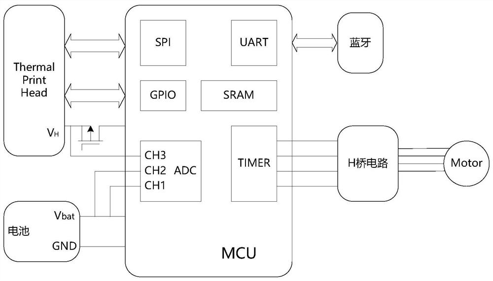
[0078] b. The switch S1 is off, the thermal print head is not powered; the switch S2 is off, the motor is off;

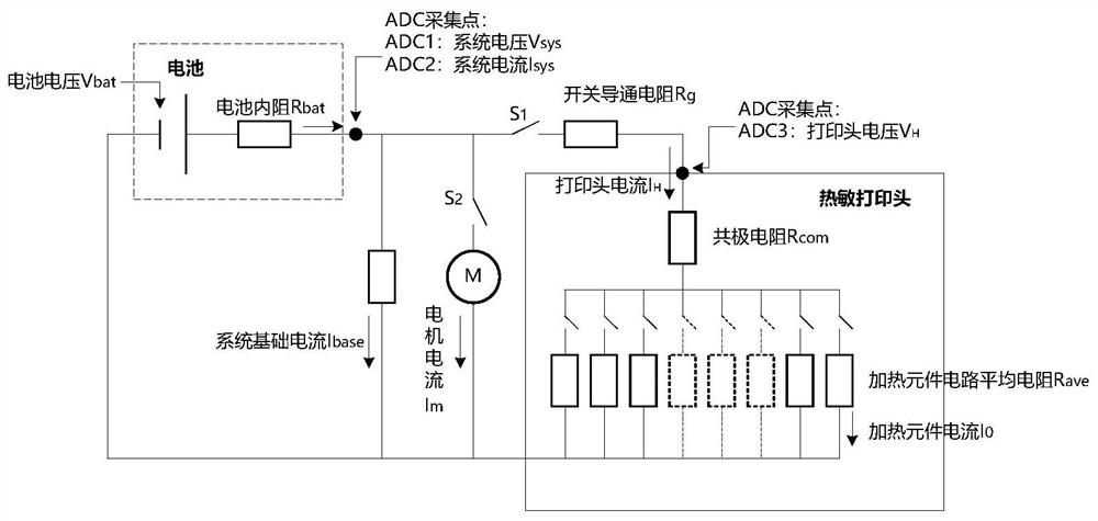
[0079] c. ADC1 and ADC2 work, respectively measure V multiple times sys , I sys , remove unreasonable sampling values, and calculate V sys and I sys The average value is used as the measured rms value of V sys [0] and I sys [0];

[0080] d. Divide the N heating points in a row on the thermal head into m1 groups, and each group has n1 heating points. The selection ...

Embodiment 2

[0092] Such as Figure 1-3 As shown, on the basis of Embodiment 1, the present invention provides a technical solution: start the motor to pre-feed the paper, and start the measurement at the same time to prepare for the official printing, including the following steps:

[0093] a) Start the motor and gradually accelerate to the predetermined speed;

[0094] a, b) Divide the N heating points in a row on the thermal head into m2 groups, each group has n2 heating points, where n2 is selected reasonably, which is the same as the number of heating points selected during normal printing, and the points in the m2 group are heated sequentially at the same time, The heating time T2 is set so as not to cause the thermal paper to develop color. During each heating period, a reasonable interval is selected to perform multiple ADC1, ADC2, and ADC3 measurements, and unreasonable sampling values ​​are eliminated, and V is calculated. sys , I sys and V H The average value is used as the m...

Embodiment 3

[0098] Such as Figure 1-3 As shown, on the basis of embodiment 1 and embodiment 2, the present invention provides a kind of technical scheme: preparation is completed, start printing, comprise the following steps:

[0099] a) get a little line from the print buffer data, carry out reasonable segmentation, obtain the point number that needs to print at present and be n3, set I mbase is the total current consumed by the system and the motor, and the formula ⑦ is obtained:

[0100] I mbase [2] = I base [2]+I m [2] = I sys [2]-I H [2] ⑦

[0101] The equivalent resistance of the system and the two circuits of the motor is Rmbase; it can be obtained from any of the following formulas ⑧ and ⑨:

[0102]

[0103] or:

[0104] b) Calculate the equivalent resistance R of the print head path when the current number of printing points is n3 H [3]: by the formula

[0105] ⑩or Calculate the total resistance R[3] of the system:

[0106]

[0107]

[0108] c) When the num...


PUM


Abstract

The invention discloses a circuit device and method for improving consistency of thermal printing concentration, and relates to the technical field of thermal printers. The method comprises the stepsof measuring and calculating battery voltage Vbat, battery internal resistance Rbat, conduction resistance Rg of a thermal printing head power supply switch, starting a motor for pre-feeding paper, measuring Vsys, Isys and VH when heating n points simultaneously, calculating the total current flowing through a printing head circuit during pressurization, obtaining current to-be-printed data, calculating the number of current to-be-heated points, calculating the heating time T under the current concentration requirement, and performing printing. According to the circuit device and method, through reasonable circuit design, the current and the voltage of the system and the voltage on a thermosensitive head are measured in the heating process, the next VH voltage is calculated according to the current heating point number and the next heating point number, and the relatively accurate power-on time is further calculated, so that the purpose of controlling the concentration consistency is achieved.

Description

technical field [0001] The invention relates to the technical field of thermal printing, in particular to a circuit device and a method for improving the density consistency of thermal printing. Background technique [0002] The principle of a thermal printer is that a semiconductor heating element is installed on the print head, and the heating element generates heat when it is energized. After the thermal printing paper contacts it, a chemical reaction occurs and the color develops, thereby printing out the desired pattern. [0003] With the maturity of thermal printing technology and lithium battery technology, the application of thermal printers has become more and more extensive, and more mobile and portable thermal printers have entered the market. When printing text, the density of the text varies from place to place, which affects the reading experience; and when printing pictures, sometimes it is required to print a certain gray scale. [0004] According to the pri...

Claims


Application Information

Patent Timeline
IPC IPC(8): B41J2/32B41J2/355B41J2/36
CPCB41J2/32B41J2/355B41J2/3558B41J2/36
Inventor 肖乐谢发炎吴涛廖建兰
Owner 北京百舸飞驰科技有限公司
Why Eureka
Try Eureka