Tunnel tunneling device and tunneling machine

A technology for tunneling and boring machines, applied in tunnels, mining equipment, earth-moving drilling, etc., can solve the problems of difficulty in timely application of initial support, many disturbances of surrounding rock, and low degree of mechanization, so as to reduce potential safety hazards, Good molding effect and high degree of mechanization

Pending Publication Date: 2021-03-05
SANY HEAVY EQUIP
View PDF0 Cites 0 Cited by
  • Summary
  • Abstract
  • Description
  • Claims
  • Application Information

AI Technical Summary

Problems solved by technology

[0003] During the construction, it is necessary to divide the section into upper and lower parts, formulate detailed excavation steps, control the roadheader to move forward and backward repeatedly, and carry out partial excavation, resulting in many procedures, low mechanization, and high labor intensity; at the same time, there are many disturbances to the surrounding rock during excavation , difficult support, resulting in low efficiency and high cost
If the section is not divided into upper and lower parts, and the whole section method is used for construction, it will easily lead to large deformation of the surrounding rock, and it will be difficult to implement the initial support in time, and there will be safety hazards of landslides and roof fall

Method used


Image

  • Tunnel tunneling device and tunneling machine
  • Tunnel tunneling device and tunneling machine
  • Tunnel tunneling device and tunneling machine

Examples


Embodiment 1

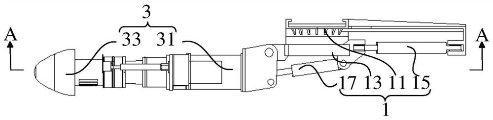
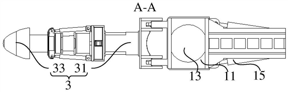
[0035] Such as figure 1 As shown, the tunnel boring device includes: two rotary devices 1, two telescopic mechanisms 2 and two cutting devices 3, wherein the two rotary devices 1 are respectively hinged to two cutting devices 3; the two telescopic mechanisms 2 are respectively connected to the two The two rotary devices 1 are connected in one-to-one correspondence. When the tunnel boring machine does not move forward and backward, the telescopic mechanism 2 can drive the rotary device 1 to move along the front and rear directions of the tunnel, thereby causing a front-rear displacement difference between the two cutting devices 3. , so that the two cutting devices 3 can carry out multi-section excavation, which is suitable for tunnel excavation by the step method, and excavates the face of the tunnel into a step shape.

[0036]Specifically, the tunnel boring device provided in this embodiment is provided with two slewing devices 1 , and the two slewing devices 1 are arranged i...

Embodiment 2

[0043] On the basis of Example 1, as Figure 4 and Figure 5 As shown, further, the telescopic mechanism 2 includes a sliding platform 21 extending forward and backward in the horizontal direction, a telescopic oil cylinder 25 and a connecting frame body 23 slidingly connected with the sliding platform 21; the rotary device 1 is arranged on the connecting frame body 23; Both ends of the oil cylinder 25 are respectively connected with the sliding platform 21 and the connecting frame body 23 for driving the connecting frame body 23 to reciprocate along the extending direction of the sliding platform 21 .

[0044] The telescopic mechanism 2 includes a sliding platform 21 , a telescopic oil cylinder 25 and a connecting frame body 23 . The upper and lower rotary devices 1 are respectively provided with upper and lower two-layer sliding platforms 21. One end of the telescopic oil cylinder 25 is connected to the sliding platform 21, and the other end of the telescopic oil cylinder 2...

Embodiment 3

[0046] On the basis of embodiment one or embodiment two, such as Figure 4 and Figure 5 As shown, further, the connecting frame body 23 extends along the length direction perpendicular to the sliding platform 21 in the horizontal direction; a sliding mechanism 27 is provided between the connecting frame body 23 and the turning device 1; the sliding mechanism 27 includes a driving member and a sliding Components; the rotary device 1 is slidably connected with the connecting frame through the sliding part, and moves along the extension direction of the connecting frame body 23 under the drive of the driving mechanism.

[0047] The tunnel boring device provided in this embodiment enables the rotary device 1 to move left and right on the basis of being able to move forward and backward, so that the rotary device 1 can move to any horizontal position, so that the tunnel face of a long-span tunnel can be excavated. Excavation. For example, the face of the upper floor is divided i...


PUM


Abstract

The invention provides a tunnel tunneling device and a tunneling machine. The tunnel tunneling device comprises a plurality of rotary devices and a plurality of telescopic mechanisms, and the rotary devices are hinged with cutting devices; the multiple telescopic mechanisms are connected with the multiple rotary devices in a one-to-one correspondence mode, and the rotary devices are constructed and arranged to be movable pieces and used for driving the cutting devices to move in the front-back direction relative to a machine body of the tunneling machine, so that front-back displacement differences are generated between the multiple cutting devices, and the multiple cutting devices can conduct multi-section excavation. The tunnel tunneling device is more independent in operation, the multiple rotary devices and the cutting devices work independently, the multiple sections are excavated through the front-back displacement differences between the multiple cutting devices, the tunnel tunneling device is suitable for excavating a tunnel through a step method, the tunneling machine does not need to be controlled to move forwards and backwards repeatedly, the construction procedures arefew, and the construction efficiency is high; and the disturbance to surrounding rock is reduced, the stability of rock mass after rock breaking work is guaranteed advantageously, and potential safetyhazards are reduced.

Description

technical field [0001] The present invention relates to the field of roadheader construction machinery, in particular to a tunnel boring device and a roadheader comprising the tunnel boring device. Background technique [0002] At present, most of the existing cantilever roadheaders are single cantilever. During excavation, the cantilever excavation structure is close to the tunnel face. The cantilever swings left and right, up and down, and cuts rocks sequentially from one side to the other. The excavation efficiency is relatively low. For this reason, a multi-cantilever roadheader is proposed, which can realize multi-point excavation and improve the tunneling efficiency. But above-mentioned tunnel boring machine is aimed at a section in the tunnel construction, for carrying out surrounding rock grade is the construction of the long-span tunnel of surrounding rock below IV level still exists following problem: [0003] During the construction, it is necessary to divide the...

Claims


Application Information

Patent Timeline
Patent Type & Authority Applications(China)
IPC IPC(8): E21D9/087E21D9/06
CPCE21D9/06E21D9/087
Inventor 杜健盖巍巍樊志家
Owner SANY HEAVY EQUIP
Why Eureka
Try Eureka