Additive manufacturing deformation control method for thin-wall partition plate type parts

A technology of additive manufacturing and deformation control, applied in the direction of additive manufacturing, additive processing, etc., can solve problems such as deformation of thin-walled isolation parts, and achieve the effect of improving surface quality, reducing deformation, and facilitating removal

Active Publication Date: 2021-03-09
CHENGDU AIRCRAFT INDUSTRY GROUP
View PDF7 Cites 5 Cited by
  • Summary
  • Abstract
  • Description
  • Claims
  • Application Information

AI Technical Summary

Problems solved by technology

[0005] In view of the above-mentioned problems and defects in the prior art, this application provides a deformation control method for additive manufacturing of thin-walled partition parts. This method uses the principle of triangular stability and has a simple structure, which can effectively solve the problem of thin-walled partition parts. deformation puzzle

Method used


Image

  • Additive manufacturing deformation control method for thin-wall partition plate type parts
  • Additive manufacturing deformation control method for thin-wall partition plate type parts
  • Additive manufacturing deformation control method for thin-wall partition plate type parts

Examples


Embodiment 1

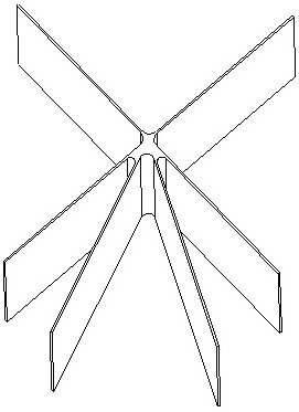
[0040] The three-dimensional number of components of the thin-walled partition component according to the present embodiment is as figure 1 As shown, the material is an aluminum alloy, and the forming method is manufactured by SLM additive. After analysis, the part size is 220 × 200 × 80mm, the thickness of the thin wall separator is 1 mm, the thin-walled part length is about 100 mm, belongs to the V-shaped part, the thin-walled structure is easy to deform, the knife, causing parts to be difficult to form .

[0041] The modification control method for manufacturing a thin-walled partition component of the present application, the steps are as follows:

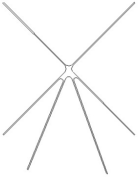
[0042] S1. Determine the placement of the part, determine the part growth direction to be parallel to each of the thin-walled partitions. The two-dimensional contour of the partial sintered part figure 2 As shown, there is no constraint in the thin plate position, which is easily deformed during the molding process, and after the...

Embodiment 2

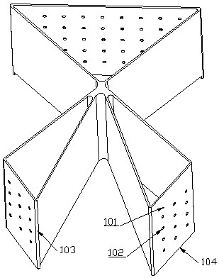
[0047] The three-dimensional number of components of the thin-walled partition component according to the present embodiment is as Figure 5 As shown, the material is a titanium alloy, and the forming method is manufactured by SLM additive. After analysis, the part size is 300 × 300 × 50mm, the thickness of the thin wall blade is 2mm, the length of the thin wall blade is about 130mm, belongs to the V-shaped part, the stress in the titanium alloy formation process, the thin-walled constitutive process is easy to deform, the knife It is difficult to form a part.

[0048] The modification control method for manufacturing a thin-walled partition component of the present application, the steps are as follows:

[0049] S1. Determine the placement of the part, determine the part growth direction to be parallel to each of the thin-walled partitions. The two-dimensional contour of the partial sintered part Figure 6 As shown, there is no constraint in the thin plate position, and the scrap...


PUM


Abstract

The invention relates to the technical field of laser advanced additive manufacturing, and discloses an additive manufacturing deformation control method for thin-wall partition plate type parts. Themethod comprises the steps that firstly, the placement mode of a part is determined, then process support is added to a thin-wall structure part in the part, the sintering shape part of each layer oflayered slice of the thin-wall structure part is closed into a triangle, importing the process model added with the process support into magics software, manufacturing by adopting an SLM (Selective Laser Melting) process additive manufacturing method, and finally carrying out post-treatment on the obtained part to obtain the product. The problems that thin-wall partition plate type parts are proneto deformation and breakage due to large stress in additive manufacturing can be effectively solved, and the success rate of additive manufacturing of thin-wall structure assemblies is greatly increased.

Description

Technical field [0001] The present application relates to the field of laser advanced additive manufacturing techniques, and more particularly to a method for producing a deformation control method for thin-walled partial parts. Background technique [0002] Additive Manufacturing, AM), also known as 3D printing, is a three-dimensional model that combines computer graphics processing, digital information, and control, laser technology, and material technology, etc., add three-dimensional model, add Support, the resilient sections are two-dimensional patterns, and the powder is filled by a laser beam, and the layer stack is stored, and the three-dimensional solid model is completed. [0003] Many thin-walled components are complex. They use conventional sheet metal, machine, and welding, parts can be achieved, and the laser 3D printing must be used, but the additive manufacturing is a process of continuous cycle, and the thin-walled parts are laser add materials. The thermal stres...

Claims


Application Information

Patent Timeline
Patent Type & Authority Applications(China)
IPC IPC(8): B22F10/28B22F10/40B22F10/47B33Y10/00
CPCB33Y10/00
Inventor 齐世文李飞黄丹唐启超林波
Owner CHENGDU AIRCRAFT INDUSTRY GROUP
Why Eureka
Try Eureka