Metal bar outer surface polishing equipment

A metal bar and outer surface technology, which is applied in the field of grinding equipment for the outer surface of metal bars, can solve problems such as poor versatility

Pending Publication Date: 2021-03-09
湖南豪镨博德新材料科技有限公司
View PDF9 Cites 4 Cited by
  • Summary
  • Abstract
  • Description
  • Claims
  • Application Information

AI Technical Summary

Problems solved by technology

Traditionally, when grinding metal rods, the clamping method is fixed, and the grinding equipment can only grind rods with the same diameter and fixed length, and the versatility is poor.

Method used


Image

  • Metal bar outer surface polishing equipment
  • Metal bar outer surface polishing equipment
  • Metal bar outer surface polishing equipment

Examples


Embodiment 1

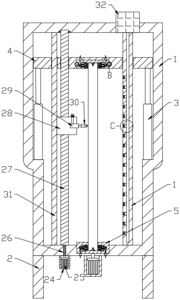
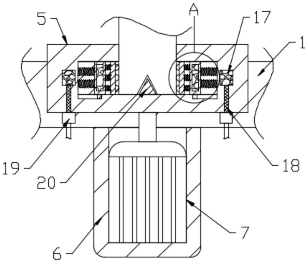
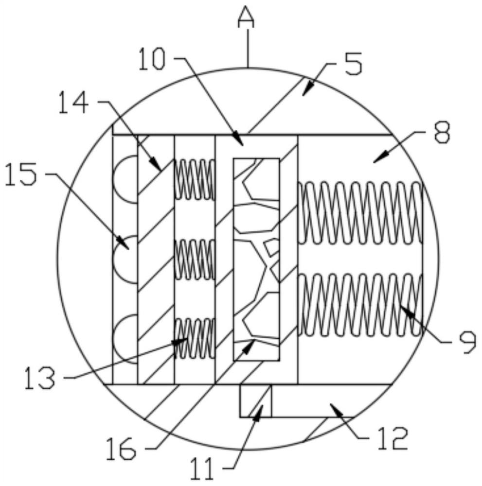
[0026] see Figure 1-6 , a metal bar outer surface grinding equipment, including a frame body 1 and a plurality of support columns 2 arranged at the lower end of the frame body 1, four first hydraulic components 3 are fixedly connected in the frame body 1, and four first hydraulic components 3 The output ends are all fixedly connected with the moving plate 4, the moving plate 4 and the frame body 1 are provided with a rotating block 5, and the frame body 1 is provided with a rotating assembly for driving the rotating block 5 to rotate, and the two rotating blocks 5 are provided with opposing The clamping assembly for clamping rods with different diameters. The rotating block 5 is provided with a working assembly that drives the clamping assembly to work. The body 1 is provided with a grinding assembly for grinding rods.

[0027] The rotating assembly includes a first chassis 6 and a first motor 7. The first chassis 6 is fixedly connected to the frame body 1. The first chassis...

Embodiment 2

[0042] Further improvements are made on the basis of Embodiment 1, and the improvements are as follows: a hot air blower 32 is provided on the upper end of the frame body 1, and an air delivery column 33 is fixedly connected in the frame body, and the air delivery column 33 runs through the movable plate 4 and is slidably connected with it , be provided with vertical cavity 34 in the gas transmission column 33, the output end of hot air blower 32 is communicated with vertical cavity 34, and the horizontal hole 35 that is provided with some transversely arranged and vertical cavity 34 is provided on the gas transmission column 35, and is provided with in the horizontal hole 35 Filter block 36; hot air blower 32 works to generate hot gas, which is transported to the horizontal hole 35 connected with it through the vertical cavity 34 on the air delivery column 33, and discharged through the horizontal hole 35, thereby realizing the removal of the leftover gas on the bar during grin...


PUM


Abstract

The invention discloses metal bar outer surface polishing equipment, and relates to the technical field of polishing. The metal bar outer surface polishing equipment comprises a frame body and a supporting column, a first hydraulic element, a moving plate and rotating blocks are arranged in the frame body, a rotating assembly is arranged on the frame body, a clamping assembly and a working assembly are arranged in each rotating block, a supporting piece is arranged between the upper rotating block and the moving plate, and a polishing assembly for polishing a bar is arranged in the frame body.The first hydraulic element in the frame body drives the moving plate fixedly connected with the first hydraulic element to move up and down, so that the distance between the clamping assembly on themoving plate and the clamping assembly on the frame body is adjusted, and bars with different lengths are clamped; and a conductive block is powered on to enable a conductive ring and a powered-on magnet to be powered on, then the powered-on magnet generates magnetism to repel a permanent magnet in a moving block, clamping blocks clamp the bar, and the bars with different diameters are clamped through the arrangement of a first spring and a second spring.

Description

technical field [0001] The invention relates to the technical field of grinding, in particular to a grinding device for the outer surface of a metal bar. Background technique [0002] Rods generally refer to a material product whose cross-sectional shape is a simple figure such as a circle, square, hexagon, octagon, etc., and whose length is relatively large compared to the cross-sectional size, and is usually provided in a straight strip. After cutting the metal bar, it is usually necessary to grind the surface of the bar. On the one hand, it can avoid the unevenness or burrs on the end surface of the bar, which will bring inconvenience to the worker's handling process. On the one hand, it is necessary to be able to improve the machining accuracy of the bar and facilitate later welding. Traditionally, when grinding metal bars, the clamping method is fixed, and the grinding equipment can only grind bars of the same diameter and fixed length, which is poor in versatility. ...

Claims


Application Information

Patent Timeline
IPC IPC(8): B24B5/04B24B41/06B24B41/02B24B55/06B24B5/35
CPCB24B5/04B24B41/062B24B41/02B24B55/06B24B5/35Y02P70/10
Inventor 赵威
Owner 湖南豪镨博德新材料科技有限公司
Why Eureka
Try Eureka