
Polishing equipment for optical glass mirror surface

A technology of optical glass and equipment, which is applied in the field of optical glass mirror grinding equipment, and can solve problems such as personnel injury, indentation, glass drop, etc.

Inactive Publication Date: 2021-03-09
广州鸿科金属材料有限公司
View PDF1 Cites 6 Cited by
  • Summary
  • Abstract
  • Description
  • Claims
  • Application Information

AI Technical Summary

Problems solved by technology

[0009] Aiming at the deficiencies of the prior art, the present invention provides an optical glass mirror polishing equipment, which solves the problem that the polishing device of the polishing machine is relatively single, and only one part of the glass surface can be polished during polishing, and the entire surface of the glass cannot be polished. Azimuth grinding, in addition, in the clamping of glass, manual clamping is required, and attention should be paid to the clamping force when clamping, which will cause indentation or cracking on the surface of the glass clamped, and in the Carry out loading and unloading, and manually move away, resulting in glass falling during transportation, and also causing physical injury to personnel. In addition, manual loading and unloading will greatly reduce the grinding efficiency.

Method used


Image

  • Polishing equipment for optical glass mirror surface
  • Polishing equipment for optical glass mirror surface
  • Polishing equipment for optical glass mirror surface

Examples


Embodiment Construction

[0035] The technical solutions in the embodiments of the present invention are clearly and completely described. Obviously, the described embodiments are only some of the embodiments of the present invention, not all of them. Based on the embodiments of the present invention, all other embodiments obtained by persons of ordinary skill in the art without making creative efforts belong to the protection scope of the present invention.

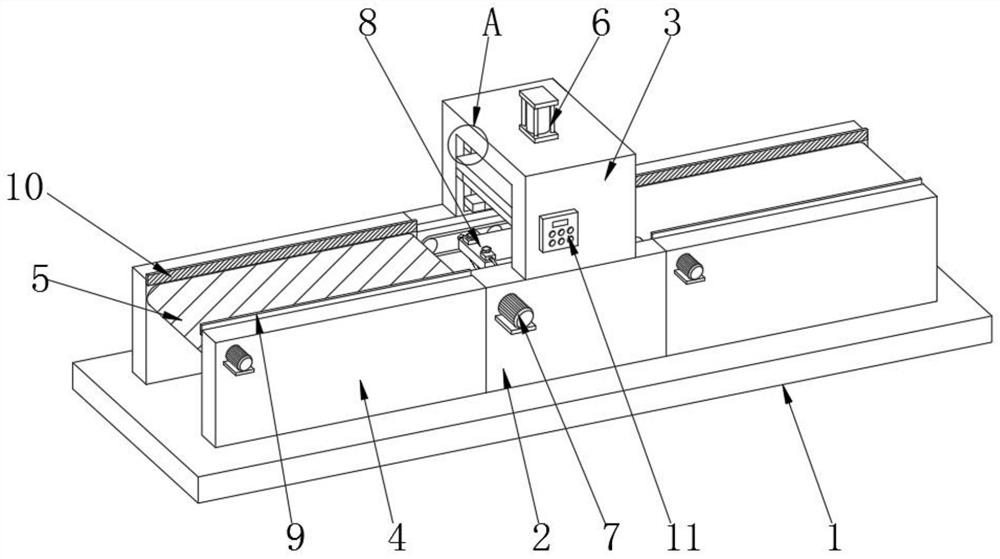
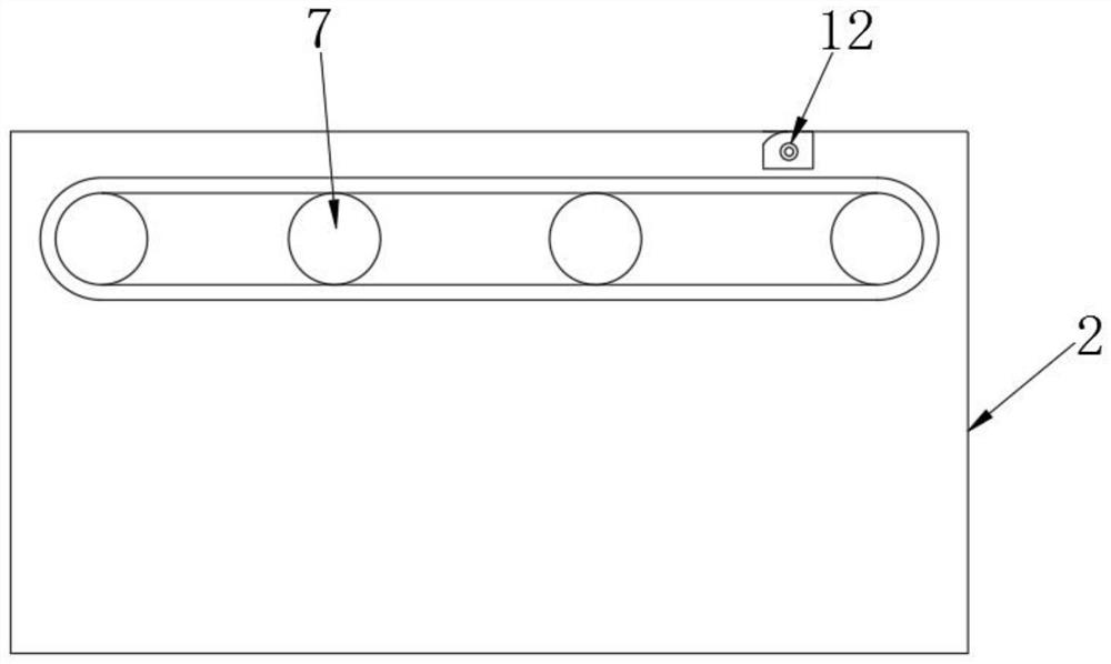
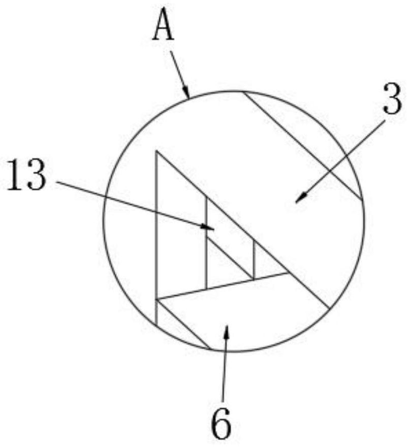
[0036] see Figure 1-3 , the embodiment of the present invention provides a technical solution: an optical glass mirror polishing equipment, including a base 1, the middle of the top of the base 1 is fixedly connected with a first fixed block 2 symmetrically, and the two ends of the first fixed block 2 are connected to the The tops of the base 1 are symmetrically fixedly connected with a second fixed block 4, the top of the first fixed block 2 is fixedly connected with a support frame 3, and an automatic polishing device 6 is arranged between the...


PUM


Abstract

The invention discloses polishing equipment for an optical glass mirror surface. The polishing equipment comprises a base, an automatic polishing device is arranged between the top of a supporting frame and an inner cavity, second conveying devices are symmetrically arranged on the opposite sides of first fixing blocks, first conveying devices are arranged on the opposite sides of second fixing blocks, and automatic adsorption devices are arranged in the middles of the first fixing blocks and on a top support of the base. The invention relates to the technical field of glass polishing. According to the polishing equipment for the optical glass mirror surface, the problems that a polishing device of a polishing machine is relatively single, the surface of glass cannot be polished in all directions, the clamping force is required to be considered during clamping, the clamped surface of the glass can be impressed or broken, when feeding and discharging are conducted, moving is conducted manually, the glass can fall off in the carrying process, the body of a person can be injured, and in addition, the polishing efficiency can be greatly reduced through manual feeding and discharging are solved.

Description

technical field [0001] The invention relates to the technical field of glass grinding, in particular to an optical glass mirror grinding equipment. Background technique [0002] Optical glass can change the direction of light propagation and change the relative spectral distribution of ultraviolet, visible or infrared light. Optical glass in the narrow sense refers to colorless optical glass; optical glass in the broad sense also includes colored optical glass, laser glass, quartz optical glass, anti-radiation glass, ultraviolet and infrared optical glass, fiber optic glass, acousto-optic glass, magneto-optical glass and photochromic Glass. Optical glass can be used to manufacture lenses, prisms, mirrors and windows in optical instruments. Components made of optical glass are key components in optical instruments, and are amorphous (glassy) optical dielectric materials that transmit light. It can be used to make various optical components such as prisms, lenses, and optic...

Claims


Application Information

Patent Timeline
Patent Type & Authority Applications(China)
IPC IPC(8): B24B13/00B24B13/01B24B13/005B24B41/00B24B55/00B24B49/12B24B47/12B24B47/14
CPCB24B13/00B24B13/005B24B13/01B24B41/005B24B47/12B24B47/14B24B49/12B24B55/00
Inventor 周铭兴
Owner 广州鸿科金属材料有限公司
Learn More