Water conservancy retaining wall structure capable of preventing water and soil loss

A retaining wall and water conservancy technology, which is applied in underwater structures, hydraulic engineering, infrastructure engineering and other directions, can solve the problems of unstable retaining wall structure, easy to be eroded by erosion, and unable to protect the slope body.

Inactive Publication Date: 2021-03-09
安徽丰之源工程建设有限公司
View PDF5 Cites 5 Cited by
  • Summary
  • Abstract
  • Description
  • Claims
  • Application Information

AI Technical Summary

Problems solved by technology

[0004] In view of the related technologies mentioned above, the inventor believes that the structure of the surface of the c

Method used


Image

  • Water conservancy retaining wall structure capable of preventing water and soil loss
  • Water conservancy retaining wall structure capable of preventing water and soil loss
  • Water conservancy retaining wall structure capable of preventing water and soil loss

Examples


Embodiment Construction

[0037] The following is attached Figure 1-5 The application is described in further detail.

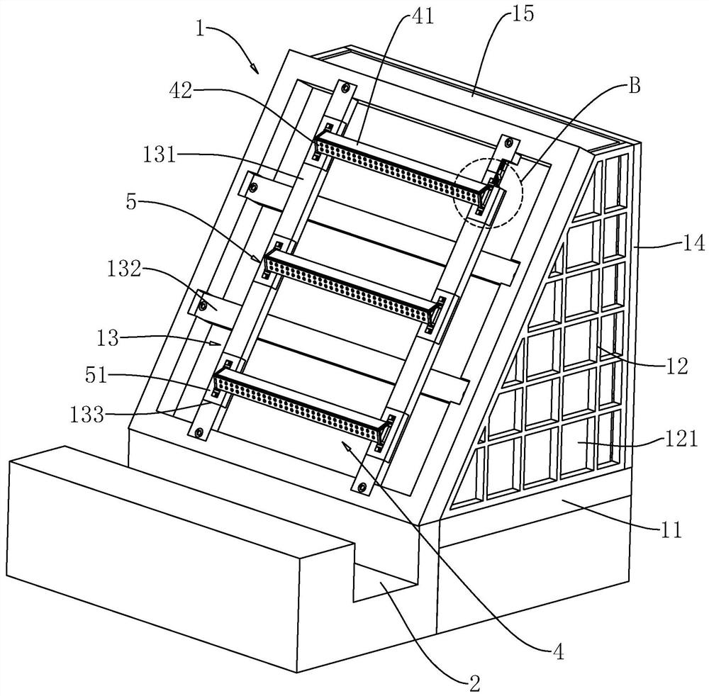
[0038] The embodiment of the present application discloses a hydraulic retaining wall structure capable of preventing soil loss. refer to figure 1, a hydraulic retaining wall structure capable of preventing soil loss, comprising a retaining wall body 1, a drainage ditch 2 is opened on one side of the retaining wall body 1, and the length direction of the retaining wall body 1 is consistent with the length direction of the drainage ditch 2 . The section of the retaining wall body 1 is a right-angled trapezoid, and the inclined waist of the retaining wall body 1 is the water-facing surface.

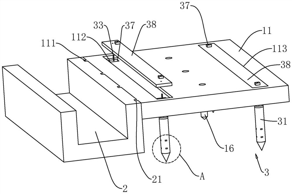
[0039] refer to figure 1 , figure 2 , the retaining wall body 1 comprises a base plate 11, a side wall plate 12, a front wall plate 13, a rear wall plate 14 and a top plate 15, the base plate 11 is in the shape of a cuboid, and the length of the base plate 11 is the same as that of the drain...


PUM


Abstract

The invention relates to a water conservancy retaining wall structure capable of preventing water and soil loss. The water conservancy retaining wall structure comprises a retaining wall body, whereinenergy dissipation assemblies and connecting assemblies are arranged on one side of the retaining wall body; a plurality of energy dissipation assemblies are arranged at intervals in the height direction of the retaining wall body; the two connecting assemblies are are respectively arranged on both ends of the energy dissipation assemblies; the energy dissipation assemblies comprise first energydissipation plates and second energy dissipation plates which are hinged to one side of the first energy dissipation plates; the connecting assemblies comprise first sliding blocks which are hinged tothe ends of the first energy dissipation plates and second sliding blocks which are hinged to the ends of the second energy dissipation plates; connecting strips are respectively arranged on the bothends of the energy dissipation assemblies; chutes are formed in the connecting strips; the first sliding blocks and the second sliding blocks which are located on the same ends of the energy dissipation assemblies are arranged in one chute in a sliding mode; and connecting springs are respectively arranged between one groove wall of the chute and the first sliding block as well as between the other groove wall of the chute and the second sliding block. The water conservancy retaining wall structure has the effect of increasing the structural stability of a retaining wall.

Description

technical field [0001] The present application relates to the field of retaining walls, in particular to a hydraulic retaining wall structure capable of preventing soil loss. Background technique [0002] At present, a retaining wall refers to a structure that supports roadbed fill or hillside soil and prevents the deformation and instability of fill or soil. [0003] The existing Chinese invention patent with the notification number CN104532875A discloses a retaining wall for water conservancy projects. The strength of the concrete wall is strengthened through the basalt weaving layer, and the keel and the concrete pouring layer are enlarged by setting a fixing frame on the keel. The connecting area is large, and the reinforcing ribs set between the fixed frames can form a triangular support structure with the keel. [0004] In view of the related technologies mentioned above, the inventor believes that the structure of the surface of the concrete wall is easily eroded by ...

Claims


Application Information

Patent Timeline
IPC IPC(8): E02D29/02E02B3/06
CPCE02B3/066E02D29/0233
Inventor 徐祖卫程家升程家洲
Owner 安徽丰之源工程建设有限公司
Why Eureka
Try Eureka