Cable sheath separating device for power construction
A technology for cable sheathing and electric power construction, which is applied in the direction of cable installation devices, cable installation, dismantling/armored cable equipment, etc., which can solve the problems of extended working hours, low degree of automation, and inability to drive cables, etc., to achieve improved Separation efficiency, high degree of automation, and the effect of saving working time
- Summary
- Abstract
- Description
- Claims
- Application Information
AI Technical Summary
Problems solved by technology
Method used
Image
Examples
Embodiment 1
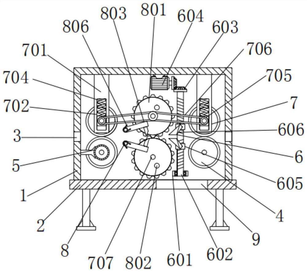
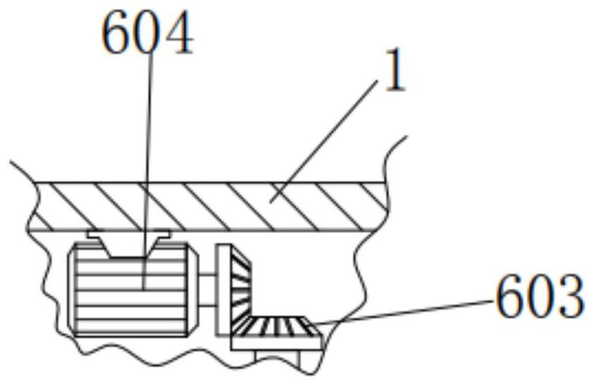
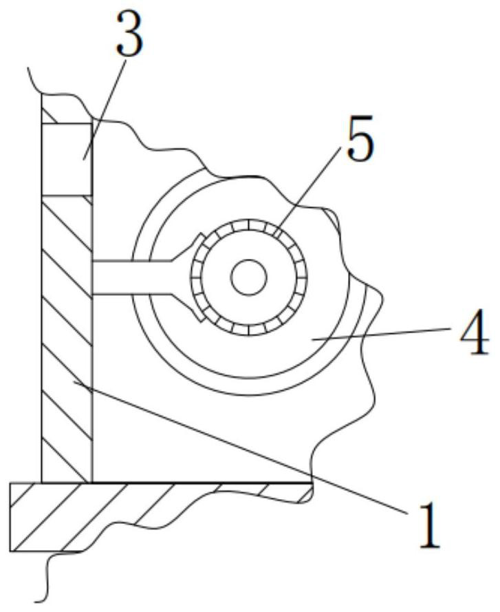
[0031] A cable sheath separation device for electric power construction, comprising a box body 1, the bottom of the box body 1 is fixedly connected with an underframe 2, the underframe 2 supports the box body 1, and an opening is processed on the right side of the top of the bottom frame 2 9. The opening 9 is used to discharge the sheath. The left and right ends of the box body 1 are processed with through holes 3. The through holes 3 are used for wiring. The inside of the box body 1 is provided with four guide wheels 4, four guide wheels 4 The interior of the box body 1 is distributed in a matrix, and it is arranged horizontally corresponding to the position of the through hole 3. This design makes the guide wheel 4 play a role in the horizontal transmission of the cable. The bottom of the inner wall of the body 1 is rotationally connected, and the rotating shaft of the guide wheel 4 on the lower left side is fixedly connected to the output end of the first motor 5. The left ...
Embodiment 2
[0034] As an option, see figure 1 with 6, the cable sheath separation device for electric power construction, the front of the guide wheel 4 above is provided with a moving assembly 7, and the moving assembly 7 includes a vertical plate 701, a vertical groove 702, a slider 703, a compression spring 704, a sheave 705, a belt 706 and The round rod 707, the top of the vertical plate 701 is fixedly connected with the top of the inner wall of the box body 1, the front of the vertical plate 701 is processed with a vertical groove 702, the inner wall gap of the vertical groove 702 is matched with a slider 703, and the vertical groove 702 is connected to the slider 703 To the guiding effect, the inner wall of the slider 703 is rotatably connected with the rotating shaft of the guide wheel 4 above, the top of the slider 703 is provided with a compression spring 704, the bottom of the compression spring 704 is fixedly connected with the top of the slider 703, and the top of the compress...
Embodiment 3
[0037] As an option, see figure 1 , 4 And 5, the cable sheath separation device for electric power construction, the inside of the box body 1 is provided with a segment assembly 8, and the segment assembly 8 includes a second gear 801, a clamping lever 802, a driving lever 803, a second cutter 804, a rotating rod 805 and torsion spring 806, the inner wall of the second gear 801 is affixed to the outer wall of the round rod 707, the inner end of the second gear 801 is meshed and connected, the second gear 801 can rotate relatively, and the front of the second gear 801 is fixedly connected with a clamping rod 802, the left side of the second gear 802 is provided with a driving lever 803, every circular movement of the locking lever 802 can drive the driving lever 803 to swing once, and the driving lever 803 and the locking lever 802 are arranged symmetrically with respect to the second gear 801, so that the design makes The driving rod 803 can cut the cable outer sheath in sect...
PUM
 Abstract
Description
Claims
Application Information
 - R&D
- Intellectual Property
- Life Sciences
- Materials
- Tech Scout
- Unparalleled Data Quality
- Higher Quality Content
- 60% Fewer Hallucinations
Browse by: Latest US Patents, China's latest patents, Technical Efficacy Thesaurus, Application Domain, Technology Topic, Popular Technical Reports.
© 2025 PatSnap. All rights reserved.Legal|Privacy policy|Modern Slavery Act Transparency Statement|Sitemap|About US| Contact US: help@patsnap.com


