Water pump pipeline flange connecting equipment and manufacturing process thereof

A pipeline flange and connecting equipment technology, applied in the field of mechanical processing, can solve the problems of slow welding speed, high workpiece structure requirements, and low production efficiency, and achieve the effects of fast welding speed, good transmission effect, and high production efficiency

Active Publication Date: 2021-03-12
ZHEJIANG BOWEI PUMP CO LTD
7 Cites 1 Cited by

AI-Extracted Technical Summary

Problems solved by technology

[0002] The liquid transportation of the water pump is generally realized through pipelines, and the pipelines need to be divided later, and the connection between multiple branch pipes and the main pipe is realized, and the flange is an indispensable mechanical part for the interconnection of tubular equipment. At present, due to the structure of the workpiece Restrict and reduce post-processing procedures. The welding joints between the elbow and the flange are generally located on the back of the flange sealing surface and are usually welded by hand. Therefore, the welding quality is unstable, the work efficiency is low, and the labor intensity is high. Arc light will be generated during machine welding, which seriously affects the health of workers, especially the damage to eyes
[0003] In order to solve this problem, some advanced enterprises have begun to use automatic welding, but the welding speed of the equipment is slow, and the requirements for the structure of the workpiece are high, so the production efficiency is low and the application range is n...

Method used

The top both sides of each slide table 19 are also provided with workpiece fixture 20 respectively, and this fixture 20 comprises cylinder 21 and hold down bar 22, and hold down bar 22 is horizontally arranged and one end is connected with cylinder 21, slide table 19 is positioned at the side of cylinder 21 and is provided with positioning block 23, is connected with rotating part 24 by thread on the positioning block 23, and the mode of operation of this workpiece fixing device 20 is: when putting into workpiece, cylinder 21 drives compression rod 22 to rise, and positioning The setting of block 23 can effectively make the placement position of the workpiece more accurate, and then rotate the tightening part manually to make it preliminarily compress the workpiece, and then the cylinder 21 descends to fix the workpiece. Similarly, when the workpiece is taken out after welding is completed, the Rotary member 24 unclamps cylinder 21 and rises.
The top of wire feeder 7 is fixedly connected with support rod 28, and the top of support rod 28 is fixedly connected with circular shaft 29, and...

Abstract

The invention provides water pump pipeline flange connecting equipment and a manufacturing process thereof, and belongs to the technical field of machining. The problems that the production efficiencyis low, and the application range is not wide as existing equipment is low in welding speed and high in requirement for a workpiece structure are solved. The water pump pipeline flange connecting equipment comprises a support, a mounting table, a welding device and a pushing device, wherein the welding device comprises wheel discs, a welding gun and a wire feeder; the welding gun is fixedly connected to the edges of the bottom surfaces of the wheel discs and is driven to rotate through rotation of the wheel discs;, the wire feeder is arranged above the wheel discs, and welding wires penetratethrough the wheel discs to be applied to the welding gun below; a circle of first-level conducting rings and two circles of second-level conducting rings are arranged between the wheel disc and the wire feeder, a speed reducer is fixedly connected to the position, located on the back surfaces of the wheel discs, of the mounting table, a motor connected to the speed reducer is fixedly connected tothe support, driven wheels corresponding to the wheel disc are arranged between the wheel discs, and the wheel discs are driven by chains to rotate through the speed reducer. The water pump pipelineflange connecting equipment has the advantages of being high in welding speed and wider in application range.

Application Domain

Welding/cutting auxillary devicesAuxillary welding devices +3

Technology Topic

FlangeDrive wheel +6

Image

  • Water pump pipeline flange connecting equipment and manufacturing process thereof
  • Water pump pipeline flange connecting equipment and manufacturing process thereof
  • Water pump pipeline flange connecting equipment and manufacturing process thereof

Examples

  • Experimental program(1)

Example Embodiment

[0038] The following is a specific embodiment of the present invention and a further description of the technical solutions of the present invention, but the present invention is not limited to these embodiments.
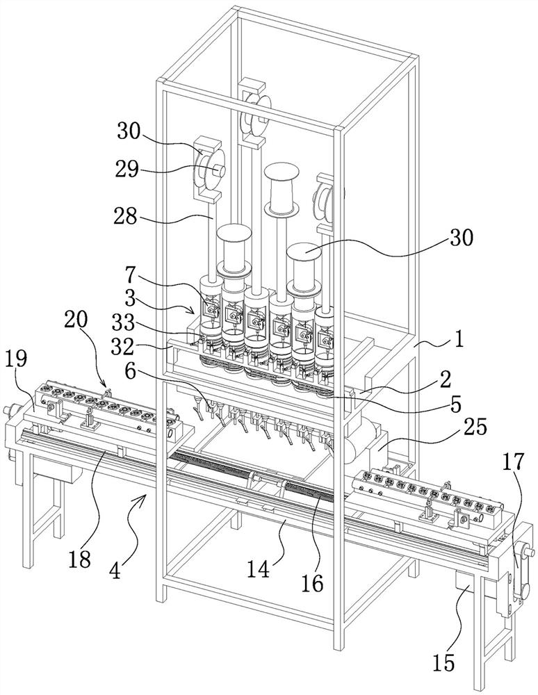
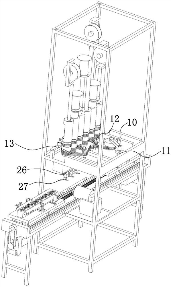
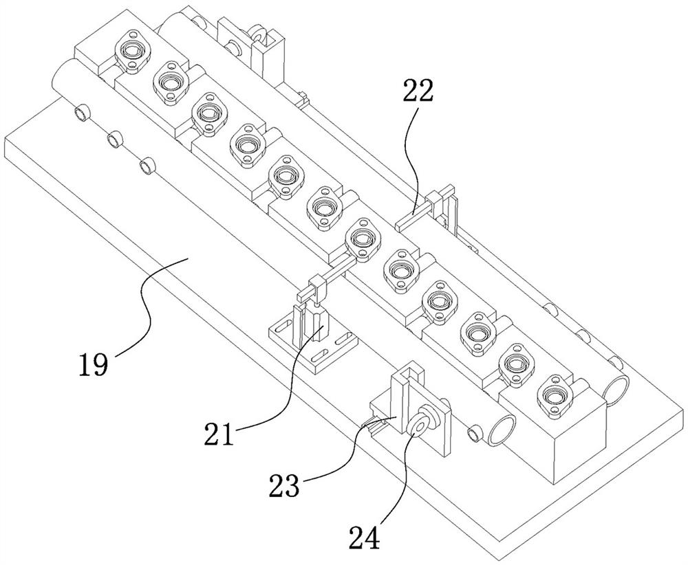
[0039] Such as figure 1 , figure 2 , image 3 , Figure 4 As shown, the pump pipeline flange is connected to the apparatus, including the bracket 1, the mounting table 2, the welding device 3, and the push device 4, and the push device 4 is horizontally passed through the bracket 1, and the middle of the bracket 1 has a rendering table 2. The welding device 3 is secured to the mounting table 2, and the welding device 3 includes a roulette 5, a soldering tuner 6, and a wire driver 7, and the number of roulettes 5 is a number of groups and uniformly arranged to each other. The welding torch is solidified in the roulette 5. The bottom edge is rotated by the wheel 5 rotation, and the wire driver 7 is disposed above the wheel 5 and the welding wire passes through the solder torch 6 applied to the bottom of the roulette, and the roulette 5 and the wire screen 7 are provided with one Circle 1-stage conductive ring 8 and two-stage secondary conductive ring 9, wherein the device power supply provides a voltage secondary conductive ring 9 for the wire gun 7 by the primary conductive ring 8, providing a voltage of the wire machine 7, and the mounting table 2 is located on the roulette 5 The back side has a reduction unit 10, and the stent 1 is firmly connected to the motor 11 connected to the reducer 10, and there is a plurality of wheel plates 5, and the wheel plate 5 is rotated by the reduction unit 10 with the chain 13. The push device 4 pushes the fixed workpiece into the welding torch 6, and the motor 11 operates the rotation of the wheel 5 to rotate through the wheel 5 to perform the rotational movement, in order to make the synchronization of the rotation between the respective roulettes 5 The chain 13 must be connected between the reducer 10, the position of the welding torch 6 is corresponding to the diameter of the flange welding, and then operates the welding torch 6 out of the wire, the welding torch 6 outlet, and the method The distance of the blue soldering surface is controlled at 7 mm. The purpose of welding is rotated by the welding torch 6. In order to make the transmission effect of the chain 13 more well, there is a driven wheel 12 corresponding to the wheel 5, the driven wheel 12 The position is located between the back side of the roulette 5 and the reducer 10.
[0040] The push device 4 includes a base 14 and a servo motor 15 disposed on both sides of the base 14. The horizontal portion of the base 14 is provided with two drive screws 16, and the outer end of the two transmission screws 16 is connected to the two servo motor 15, respectively. The base 14 is located on the outer side of the drive screw 16, and two sliders 19 are disposed above the track 18 and the two slides 19 are connected to the two screws, and the workpiece is placed above the slide 19, one of them. The side servo motor 15 is rotated to the running drive screw 16, and the slide 19 is pushed by the drive screw 16 and stops after reaching a certain position, the welding device 3 starts the start of welding, the servo motor 15 reverse operation will slip after the welding is completed. Table 19 reversed, during the workpiece welding process, the worker can use the welding time to mount the workpiece on the other side of the slide 19. When the welding is completed, the side slide 19 introduces the other side to the other side, the push device 4 Operation in mutual interval, fully utilizing the time of workers installing the workpiece, so the production efficiency is higher.
[0041] The workpiece fixing device 20 is respectively provided on both sides of each slide 19, and the fixing device 20 includes a cylinder 21 and a pressing rod 22, and the compressive rod 22 is disposed laterally and one end is connected to the cylinder 21, and the slide 19 is located on the slide 19 The positioning block 23 is provided on one side of the cylinder 21, and the positioning block 23 is connected to the rotating member 24 by a thread, and the operating mode of the workpiece fixing device 20 is: when the workpiece is placed, the cylinder 21 rises to rises, positioning block 23 The setting can effectively make the workpiece placement position more accurate, then rotate the rotating member by manual manually, so that the workpiece is initially pressed, and the cylinder 21 is fixed down, and the workpiece will be rotated when the workpiece is removed after welding. Loosen the cylinder 21 to rise.
[0042] The cylinder 25 is provided in the bracket 1, and the lower solids in the mounting table 2 has a hydraulic rod 26 that matches each solder torch 6, and the hydraulic rod 26 is connected to the cylinder 25 to make it up and down by hydraulic, hydraulic rod 26 The bottom end is inherently having a pressure plate 27, the pressure plate 27 is a circular arc structure and the connection portion of the hydraulic rod 2 is in which the hydraulic rod 26 operates down by the cylinder 25, and functions to fix the workpiece. It can effectively prevent the workpiece from being displaced during the welding process, making the welding effect, wherein the length of the pressure plate 27 is matched to the structure requiring the welding workpiece.
[0043] Above the feeder 7 has a strut 28, and the top of the strut 28 is fixedly coupled, and the circular shaft 29 is provided with a filament disk 30, wherein the height of each of the strip 28 is inconsistent, the circular shaft 29 is The connection structure between the struts 28 is laterally connected to vertically, the advantage of the connection structure, since the bracket 1 has limited space, the welding device 3 during operation, the rod 28 is synchronously rotated by the ribbon 30, passed The height of the strut 28 is staggered and the mounting of the filament disc 30 is disposed to be lateral vertical intervals, facilitating the mounting of the filament disc 30 and can prevent the wire from touching.
[0044] An air disc ring 31 is provided above the wheel 5, and the gas flow path thereof is connected to the weld gun 6 by the gas flow path thereof. The welding type is air welding, and since the roulet 5 needs to be rotated during the welding process, the gas pipe is formed from being wrapped through the arrangement of the airway 31.
[0045] The bracket 1 is located above the mounting table 2, and the crossbar 32 is provided on the crossbar 32, and the number of carbon brushes 33 connected to the primary conductive ring 8 and the secondary conductive ring 9, and the number of solder torches is 6. The number of driven wheels 12 is 4.
[0046] Further, the welding process of the flange multi-station synchronous welding device is: mounting the workpiece, the cylinder 21 rises to rises, placed the elbow, fixed on the slide 19 through the positioning block 23, and then press the bar 22 The down pressure of the artifact and set the flange to the interface of each elbow; place the ceramic tube in the elbow, to protect the inner wall of the elbow without producing a porcelain tube; servo motor 15 The forward operation is moved, and the slide stage is moved to the fixed position, and then the hydraulic rod 26 is lowered by the control cylinder 25, the hydraulic rod 26 is lowered, and the workpiece is fixed; the flower 7 starts running the welding torch 6, and passed The conductive ring 31 delivers carbon dioxide gas into the welding torch 6, while the motor 11 drives the wheel 5 rotary welding torch 6 to start welding, while the worker is mounted by the workpiece through the other side of the slide 19; after the welding is completed, the cylinder 25 is passed The hydraulic rod 26 rises, the servo motor 15 reverse rotates to remove the internal slide 19, and the slide 19 on the other side moves inside; place the workpiece after the welding is taken out, while placing unweld to the slide 19 The workpiece; the cooling workpiece is then polished to the welding of the flanged cover, so that its surface is flat.
[0047] The specific embodiments described herein are merely illustrative of the spirit of the invention. Those skilled in the art of the present invention can make a wide variety of modifications or supplements or replacement in a similar manner, but will not deviate from the spirit of the invention or transcending the appended claims. Range.
[0048] Although the bracket 1, the mounting table 2, the welding device 3, the push device 4, the wheel 5, the welding torch 6, the flowing machine 7, the primary conductive ring 8, the secondary conductive ring 9, and the reducer 10, The electric motor 11, the driven wheel 12, the chain 13, the base 14, the servo motor 15, the drive screw 16, the synchronization belt 17, the track 18, the slide stage 19, the fixing device 20, the cylinder 21, the pressing rod 22, the positioning block 23, rotating member 24, the cylinder 25, the hydraulic rod 26, the pressure plate 27, the strut 28, the circular shaft 29, the filament disc 30, the guiding ring 31, the crossbar 32, the carbon brush 33, etc., but does not exclude the possibility of using other terms. These terms are used only to more easily describe the nature of the present invention;

PUM

no PUM

Description & Claims & Application Information

We can also present the details of the Description, Claims and Application information to help users get a comprehensive understanding of the technical details of the patent, such as background art, summary of invention, brief description of drawings, description of embodiments, and other original content. On the other hand, users can also determine the specific scope of protection of the technology through the list of claims; as well as understand the changes in the life cycle of the technology with the presentation of the patent timeline. Login to view more.

Similar technology patents

Winding device utilizing motor for driving

InactiveCN108100760Astable structureGood transmission effect
Owner:佛山市万良商贸有限公司

Compensator driving device and compensator

PendingCN110253746AGood transmission effectreduce friction
Owner:KEDA INDUSTRIAL GROUP CO LTD

Movable directional transmission lifting platform

InactiveCN112607675ASimple structureGood transmission effect
Owner:XIAN AERONAUTICAL POLYTECHNIC INST

Gravity sliding power machine

PendingCN114687969AGood transmission effectPower generation effect is good
Owner:张有志

A water throwing device driven by friction wheel

InactiveCN102287899AGood transmission effectimprove energy efficiency
Owner:CI XI TUO YING ELECTRICAL

Classification and recommendation of technical efficacy words

  • Increase productivity
  • Good transmission effect

Preparation method of super-retarding type polycarboxylate superplasticizer

ActiveCN103848944AIncrease productivityUniform product
Owner:KZJ NEW MATERIALS GROUP CO LTD

Hollow motor

InactiveCN104600902AReduce transmission ring damageGood transmission effect
Owner:广东韦达尔传媒有限公司 +1

Burr polishing equipment for hardware accessory machining

PendingCN111203783AGood transmission effectWide range of applications
Owner:宁波佳禾五金配件有限公司

Container and cover transiting-transferring manipulator

PendingCN108974445AImprove work efficiencyGood transmission effect
Owner:王贤淮

Intersectional shrapnel transmission shoes

InactiveCN101228979AGood transmission effectEven by force
Owner:曾烃

Vertical folded plating production line

InactiveCN102146575Ashorten the lengthGood transmission effect
Owner:黄方豹
Why Eureka
Try Eureka