Automatic hoisting equipment, hoisting method and lifting method

A hoisting equipment and automatic technology, applied in the direction of safety devices, transportation and packaging, load hanging components, etc., can solve the problems of non-adjustable magnetic penetration depth, difficult, laborious operation, etc., and achieve the effect of easy automatic implementation and simple steps

Pending Publication Date: 2021-03-12
ZHUZHOU HVR MAGNETICS
View PDF6 Cites 0 Cited by
  • Summary
  • Abstract
  • Description
  • Claims
  • Application Information

AI Technical Summary

Problems solved by technology

This kind of suction and discharge process requires manual operation, and the labor intensity of personnel is high. Moreover, when encountering thin workpieces such as steel plates, because the magnetic circuit is not smooth, the handle may not be able to rotate, which is laborious and difficult to operate.
Moreover, this kind of spreader also has the situation that the depth of magnetic penetration cannot be adjusted, and it is impossible to realize single-piece lifting of thin workpieces
[0004] The automatic spreader relies on the self-weight of the spreader to drive the magnetic pole to rotate to realize material suc

Method used


Image

  • Automatic hoisting equipment, hoisting method and lifting method
  • Automatic hoisting equipment, hoisting method and lifting method
  • Automatic hoisting equipment, hoisting method and lifting method

Examples


Embodiment 1

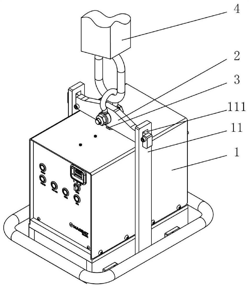
[0052] Such as figure 1 As shown, the automatic hoisting equipment of this embodiment includes an electro-permanent magnet hoist 1 for hoisting workpieces and a connecting device 2 connected to the hoisting trolley 4, and the electro-permanent magnet hoist 1 is movably connected to the connection in the vertical direction On the device 2, the automatic hoisting equipment also includes a device for detecting the relative positional relationship between the electro-permanent magnet hoist 1 and the connecting device 2, and feeding back the detection signal to a control system to control whether the electro-permanent magnet hoist 1 performs adsorption on the workpiece. And the detection device 3 of release action. Since the electro-permanent magnet hoist 1 and the connecting device 2 can move along the vertical direction, the positional relationship between the two will change when the hoisting equipment is hoisted and landed.

[0053] During the hoisting process, the automatic h...

Embodiment 2

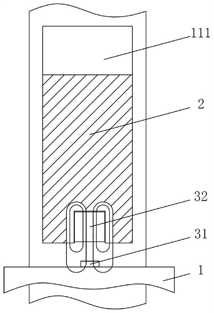
[0081] This embodiment is basically the same as Embodiment 1, the difference is that in this embodiment, such as Figure 4As shown, the detection device 3 includes a proximity switch 33. The proximity switch 33 is installed on the electro-permanent magnet hanger 1 or the connection device 2. The proximity switch 33 can flexibly capture the distance between the electro-permanent magnet hanger 1 and the connection device 2. Changes in positional relationships. The distance between the electro-permanent magnet lifter 1 and the connecting device 2 detected by the proximity switch 33 is less than the second set value, that is, when the hoisting equipment lands, the electro-permanent magnet lifter 1 is controlled to perform the adsorption or release action on the workpiece, which is greater than the second set value value, that is, control the electro-permanent magnet lifter 1 to maintain the state before it is greater than the second set value when the hoisting equipment is hoisted...

Embodiment 3

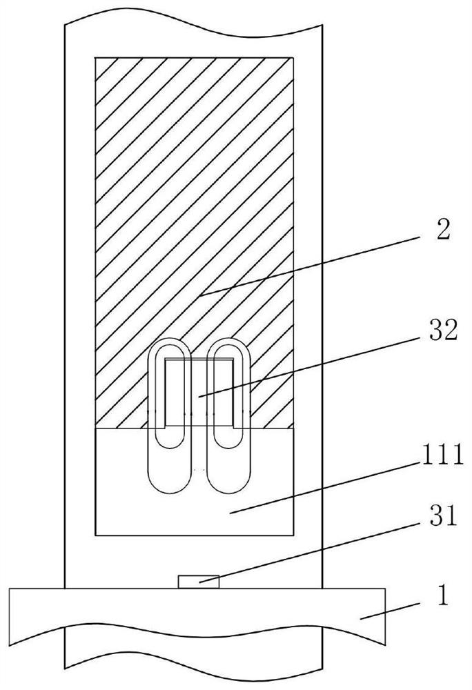
[0084] This embodiment is basically the same as Embodiment 1, the difference is that in this embodiment, such as Figure 5 As shown, the detection device 3 includes a contact switch 34 , and the contact switch 34 is disposed at at least one end of the strip-shaped hole 111 in the vertical direction. The contact switch 34 can stably detect the positional relationship between the connecting device 2 and the electro-permanent magnet hanger 1 .

[0085] When the contact switch 34 is arranged on the top of the bar-shaped hole, the contact switch 34 is in contact with the connecting device 2, which means that the connecting device 2 is in contact with the top of the bar-shaped hole 111, that is, the whole hoisting device is in the hoisting position, and the hoisting device is kept in the suction position at this time. If the contact switch 34 is not in contact with the connecting device 2, it means that the connecting device 2 is not in contact with the top of the strip hole 111, th...


PUM


Abstract

The invention discloses automatic hoisting equipment, a hoisting method and a lifting method. The hoisting equipment comprises an electric permanent magnet lifting appliance used for hoisting a workpiece and a connecting device connected with a hoisting trolley, and the electric permanent magnet lifting appliance is movably connected to the connecting device in the vertical direction; and the automatic hoisting equipment further comprises a detection device used for detecting the relative position relation between the electric permanent magnet lifting appliance and the connecting device and feeding back a detection signal to a control system so as to control whether the electric permanent magnet lifting appliance carries out adsorption and release actions on the workpiece or not. The automatic hoisting equipment has the advantages of being simple, practical, capable of reducing the labor intensity of personnel and effectively reducing errors and risks, high in automation degree and thelike, the hoisting method and the lifting method have the advantages that besides the advantages, the steps are simple, operation is easy and convenient, and safety can be improved while hoisting ofa single piece is guaranteed.

Description

technical field [0001] The invention relates to the technical field of workpiece lifting, in particular to an automatic lifting device, a lifting method and a lifting method. Background technique [0002] Hoisting equipment is often used in steel, logistics, transportation, machinery manufacturing and other industries. Among them, electromagnetic spreaders, as a safe, economical and environmentally friendly magnetic material spreader, are widely used. Commonly used electromagnetic spreaders include permanent magnet spreaders, electromagnet magnetic spreaders, and electro-permanent magnetic spreaders. [0003] In the permanent magnet type magnetic lifting device, the manual type lifting device generally uses the handle to rotate the direction of the magnetic pole to change the direction of the magnetic field inside the permanent magnet to absorb and discharge materials. This suction and discharge process requires manual operation, which has high labor intensity, and when enc...

Claims


Application Information

Patent Timeline
IPC IPC(8): B66C1/06B66C13/22B66C15/06G01D5/12
CPCB66C1/06B66C13/22B66C15/065G01D5/12
Inventor 黄大启黄斌周志朝
Owner ZHUZHOU HVR MAGNETICS
Why Eureka
Try Eureka