Variable amplitude control method, device and system for vibratory roller, and vibratory roller

A vibratory road roller and amplitude control technology, applied in the field of road rollers, can solve the problems of complex structure of road roller vibrating wheels, reduced reliability of road rollers, inconvenient manufacturing and processing, etc., and achieve the effect of simple structure, realization of amplitude, and convenient operation

Pending Publication Date: 2021-03-12
XCMG CONSTR MACHINERY
View PDF0 Cites 4 Cited by
  • Summary
  • Abstract
  • Description
  • Claims
  • Application Information

AI Technical Summary

Problems solved by technology

A typical structure is the four-axis stepless amplitude modulation mechanism proposed by BOMAG. The four exciters are installed in the inner cylinder. The two exciters in the middle rotate synchronously with the two exciters on both sides to form a directional vibration force. The shaft rotates the inner cylinder under the drive of the amplitude modulation cylinder, changing the angle between the inner cylinder and the vertical ground direction, that is, the angle between the directional vibration force and the vertical ground direction, and realizing the adjustment of the amplitude. This mechanism can realize the stepless adjustment of the amplitude, but Very complex structure
[0006] The existing amplitude adjustment method needs to be realized by changing the eccentric moment of the exciter in the vibrating wheel of the road roller or changing the direction of the exciting force. The structure of the vibrating wheel is complex, resulting in inconvenient manufacturing and processing. At the same time, the reliability of the road roller is reduced due to the use of more components

Method used


Image

  • Variable amplitude control method, device and system for vibratory roller, and vibratory roller
  • Variable amplitude control method, device and system for vibratory roller, and vibratory roller
  • Variable amplitude control method, device and system for vibratory roller, and vibratory roller

Examples


Embodiment Construction

[0053] In order to make the technical means, creative features, goals and effects achieved by the present invention easy to understand, the present invention will be further described below in conjunction with specific embodiments.

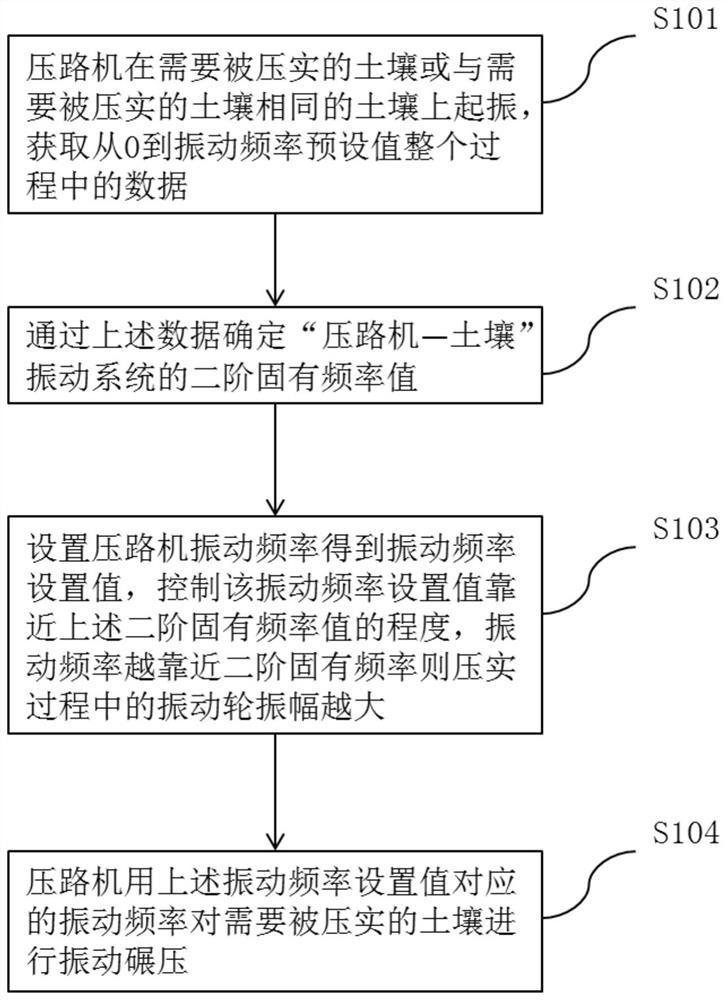
[0054] refer to figure 1 , figure 1 It is a flow chart of a vibratory roller variable amplitude control method according to an embodiment of the present invention, including the following steps:

[0055] Step S101: The road roller starts to vibrate on the soil to be compacted or the same soil as the soil to be compacted, and acquires data during the whole process from the vibration frequency from zero to the vibration frequency preset value.

[0056] The vibratory roller is a kind of construction machinery that generates centrifugal force through the high-speed rotation of the exciter assembled inside the vibrating wheel, so that the part inside the shock absorber generates continuous mechanical vibration, forcing the working medium to vibrate to...


PUM


Abstract

The invention discloses a variable amplitude control method for a vibratory roller. The method comprises the following steps: acquiring data information in the process of increasing the vibration frequency from zero to a preset value of the vibration frequency, wherein the data information is obtained by a road roller in to-be-pressed soil or soil the same as the to-be-pressed soil; obtaining a second-order inherent frequency value of the soil system of the road roller according to the data information; setting the vibration frequency of the road roller, obtaining a vibration frequency set value, and controlling the degree of the vibration frequency set value close to the second-order inherent frequency value; and controlling the road roller to vibrate and grind the soil to be pressed at the vibration frequency corresponding to the vibration frequency set value. A special vibration exciter structure or amplitude modulation oil cylinder or vibration wheel structure in the vibration wheel does not need to be adopted, the amplitude can be changed only by changing the vibration frequency, and the control method is simple and high in reliability.

Description

technical field [0001] The invention relates to the technical field of road rollers, in particular to a variable amplitude control method, device, system and road roller for vibratory road rollers. Background technique [0002] The road roller is a construction machine whose main purpose is to increase the compactness of the working medium (earth filling and road pavement mixture). The earliest road rollers were compacted by static force, that is, the static pressure generated by the weight of the road roller was used to force the working medium to be dense. The internal friction between the particles is lost, resulting in higher compaction efficiency and better compaction effect, so vibratory rollers are gradually becoming mainstream. [0003] When the vibratory roller is used for compacting fill, compacting roadbed and compacting road surface, the amplitude of the vibration wheel is also required to be different due to the different degree of compaction and the depth affe...

Claims


Application Information

Patent Timeline
Patent Type & Authority Applications(China)
IPC IPC(8): E01C19/28
CPCE01C19/28E01C19/282E01C19/286E01C19/288
Inventor 高亮夏磐夫段吉轮林栋冰朱冠亚高孔超
Owner XCMG CONSTR MACHINERY
Why Eureka
Try Eureka