Hall thruster heat conduction support and Hall thruster comprising same

A technology of Hall thruster and heat-conducting support, which is applied in thrust reverser, machine/engine, plasma utilization, etc., can solve the problems of poor thermal stability of Hall thruster with high specific impulse and high power.

Active Publication Date: 2021-03-12
HARBIN INST OF TECH +1
View PDF8 Cites 3 Cited by
  • Summary
  • Abstract
  • Description
  • Claims
  • Application Information

AI Technical Summary

Problems solved by technology

[0003] The present invention aims to solve the problem of poor thermal stability of the existing high-specific impulse and h

Method used


Image

  • Hall thruster heat conduction support and Hall thruster comprising same
  • Hall thruster heat conduction support and Hall thruster comprising same
  • Hall thruster heat conduction support and Hall thruster comprising same

Examples


specific Embodiment approach 1

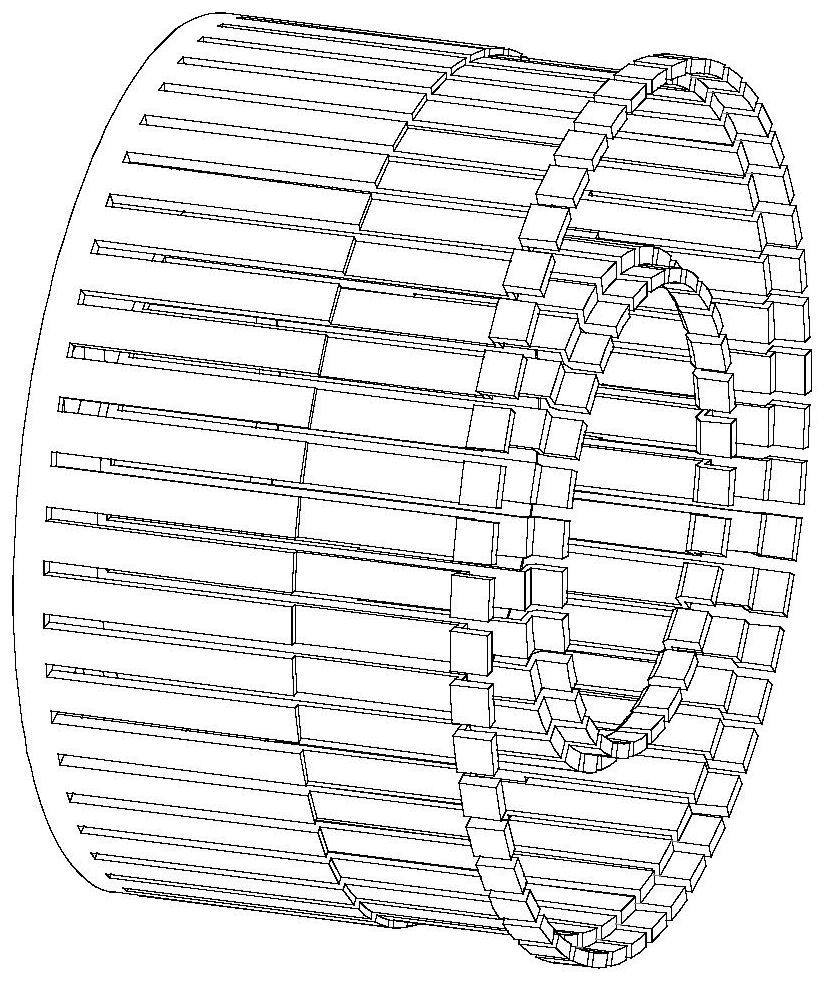
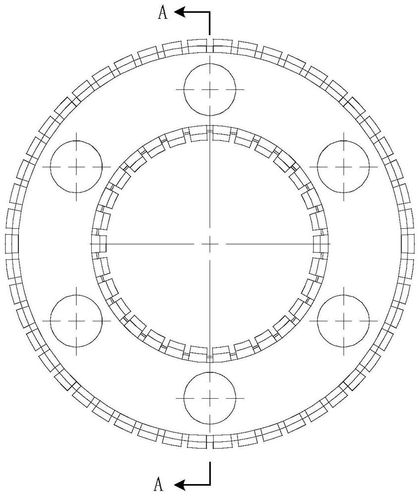
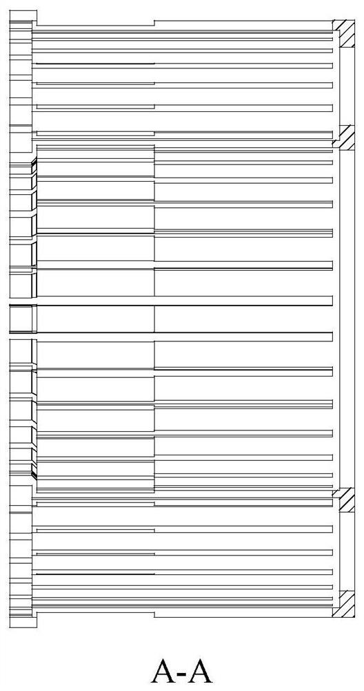
[0014] Specific implementation mode one: refer to Figure 1 to Figure 3 This embodiment is described in detail. The Hall thruster heat conduction support described in this embodiment includes two cylinders with the same length and coaxially nested inside and outside. The length of the two cylinders is both 70 mm. The same ends of the two cylinders are connected through a bottom plate, the bottom plate is ring-shaped, and a plurality of through holes uniformly arranged along its circumferential direction are arranged on the bottom plate.

[0015] Specifically, the outer diameter of the inner cylinder is the same as the inner diameter of the bottom plate, one end of the cylinder is connected to the inner ring of the bottom plate, the inner diameter of the outer cylinder is the same as the outer diameter of the bottom plate, and one end of the cylinder is connected to the outer ring of the bottom plate.

[0016] Considering that the high-energy particles of the Hall thruster main...

specific Embodiment approach 2

[0022] Specific implementation mode two: refer to Figure 4 and Figure 5 Describe this embodiment in detail. This embodiment is a Hall thruster including the heat conduction bracket of the Hall thruster described in Embodiment 1. The heat conduction bracket 7 of the Hall thruster is covered outside the discharge channel 6 of the Hall thruster. The distance between the inner cylinder and the inner magnetic shield 4 of the Hall thruster heat conduction bracket 7 is 1.5 mm, and the surface of the inner magnetic shield 4 opposite to the inner cylinder is electroplated to reduce the surface radiation Coefficient, to reduce the heat radiation power of the Hall thruster heat conduction bracket to the inner magnetic shield 4.

[0023] An aluminum Hall thruster heat conduction bracket 7 is added outside the ceramic discharge channel 6 of the traditional Hall thruster to guide the heat flow generated on the discharge channel 6, and guide the heat flow on the inner ceramic to the exter...


PUM

PropertyMeasurementUnit
Thicknessaaaaaaaaaa
Thicknessaaaaaaaaaa
Lengthaaaaaaaaaa

Abstract

The invention discloses a Hall thruster heat conduction support and a Hall thruster comprising the same, and relates to a heat dissipation structure of the Hall thruster. The invention aims to solve the problem of low heat stability of an existing high-specific-impulse high-power Hall thruster. The Hall thruster heat conduction support comprises two cylinders which are the same in length and are coaxially nested inside and outside, wherein the same ends of the two cylinders are connected through a bottom plate; a plurality of through holes are formed in the bottom plate; a plurality of gaps with one ends open and the other ends closed are formed in the cylinder walls of the two cylinders; the plurality of gaps are evenly distributed in the circumferential direction of the cylinder; the trend of the gaps is the same as the axial direction of the cylinders; and the open ends of the gaps are communicated with the open ends of the cylinders. According to the Hall thruster heat conduction support, most wall surface deposition heat flow is conducted to an external member with high heat dissipation capacity of the Hall thruster, so that heat deposition of an internal magnetic circuit of the Hall thruster is reduced, the overall heat dissipation capacity of the Hall thruster is enhanced, and finally the overall heat stability of the Hall thruster is improved.

Description

technical field [0001] The invention belongs to a Hall thruster, in particular to a ceramic heat dissipation structure of a Hall thruster. Background technique [0002] As one of the electric propulsion devices that have been used in orbit, the thermal stability of the Hall thruster is the core issue that has attracted widespread attention. During the process of the ions in the discharge channel of the Hall thruster being ejected by the acceleration of the electric field and generating thrust, some ions will interact with the wall of the discharge channel, that is, the ions are sputtered to the wall, resulting in energy loss. This part of the lost energy is mainly deposited in the form of heat energy at the outlet section of the wall surface of the discharge channel, and the heat deposition power on the wall surface can reach 20% to 30% of the total power. At the same time, with the increase in the demand for space missions with high power and high specific impulse, the Hal...

Claims


Application Information

Patent Timeline
IPC IPC(8): F03H1/00
CPCF03H1/0087
Inventor 宁中喜夏国俊于达仁刘强
Owner HARBIN INST OF TECH
Why Eureka
Try Eureka