Gradient utilization device for diffused gas self-sustaining catalytic combustion sensible heat

A technology for releasing gas and catalytic combustion, applied in the combustion method, combustion type, combined combustion mitigation, etc., can solve problems such as energy waste, lack of feedback from control systems, and inability to meet the needs of self-sustaining catalytic gas temperature, to reduce emissions, The effect of improving the scope of applicability and work efficiency, and improving the utilization efficiency of waste heat resources

Inactive Publication Date: 2021-03-12
INST OF MECHANICS - CHINESE ACAD OF SCI
View PDF12 Cites 2 Cited by
  • Summary
  • Abstract
  • Description
  • Claims
  • Application Information

AI Technical Summary

Problems solved by technology

[0003] In related technologies, the method of front-end combustion + back-end catalysis is often used to post-treat the vented gas and recover waste heat, but it ignores that in actual operation, the concentration of carbon monoxide in the back-end gas is usually lower than 10%, and the 10% concentration of carbon monoxide in the vented gas is self-sustaining and catalyzed The gas inlet temperature is required to be above 150°C
However, under operating conditions, the gas temperature after sensible heat utilization in the middle section is usually less than 150°C, especially in low-temperature environment experiment conditions (winter), the inlet temperature of the catalytic system is less than 100°C, which cannot meet the gas temperature requirements of self-sustaining catalysis
[0005] Although the above method discloses some utilization methods, these catalytic heat exchangers only have one-stage catalytic reaction waste heat recovery and utilization, and there is a certain waste of energy. At the same time, there is also a lack of control system to form feedback on the operation process of the device.

Method used


Image

  • Gradient utilization device for diffused gas self-sustaining catalytic combustion sensible heat

Examples


Embodiment Construction

[0015] The specific structure and implementation process of this solution will be described in detail below through specific embodiments and accompanying drawings.

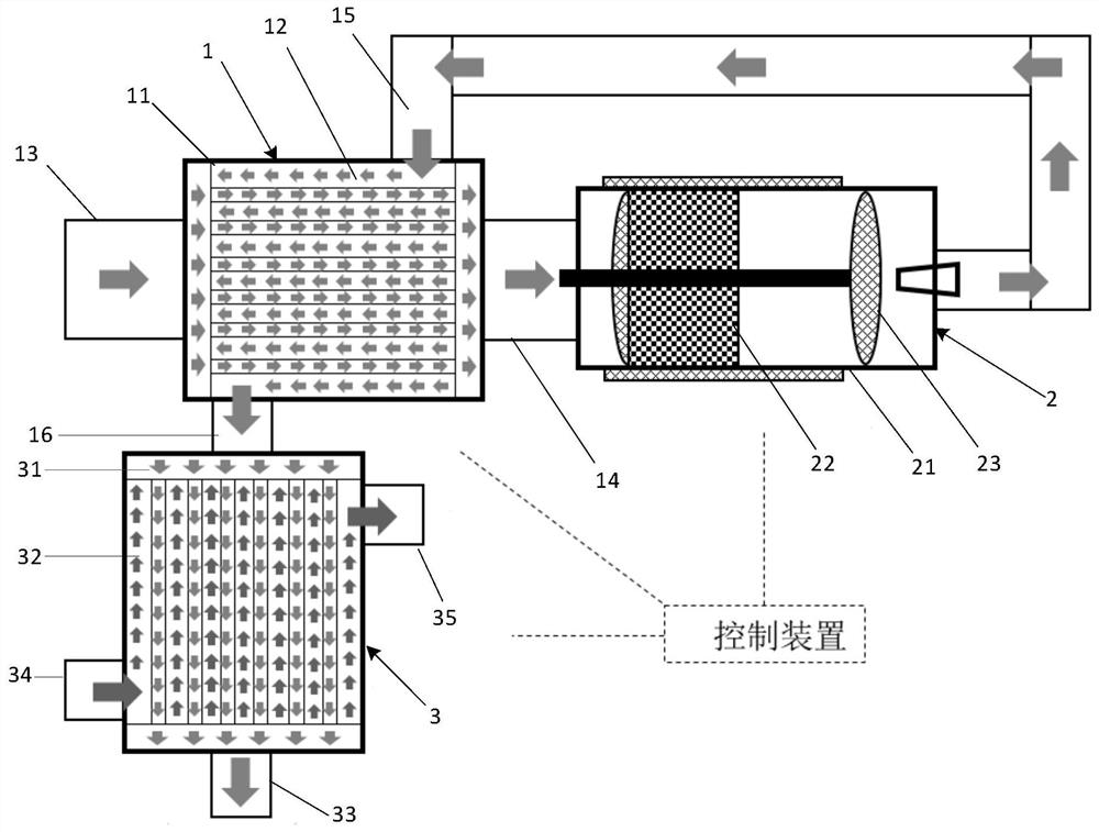
[0016] Such as figure 1 As shown, in one embodiment of the present invention, a self-sustaining catalytic combustion sensible heat cascade utilization device for vented gas is disclosed, including a preheating device 1 , a catalytic combustion device 2 , a sensible heat recovery device 3 and a control system 4 .

[0017] The preheating device 1 includes a preheating chamber 11 with a preheating pipeline 12 inside, a gas inlet 13 connected to the flue is connected to the preheating chamber 11, and a gas outlet 14 that releases the gas after outputting preheating, and is connected with the preheating chamber 11. The high temperature inlet 15 and the high temperature outlet 16 are respectively connected at both ends of the preheating pipeline 12; the flue is used as a smoke exhaust channel for converter steelmaking t...


PUM


Abstract

The invention provides a gradient utilization device for diffused gas self-sustaining catalytic combustion sensible heat. The gradient utilization device comprises a preheating device and a preheatingcavity internally provided with a preheating pipeline, and a gas inlet and a gas outlet are connected with the preheating cavity; the two ends of the preheating pipeline are connected with a high-temperature inlet and a high-temperature outlet separately; a catalytic combustion device comprises a shell, a carrier and a coating, and the carrier and the coating are installed in the shell; the two ends of the shell are connected with the gas outlet and the high-temperature inlet separately; a sensible heat recovery device comprises a heat exchange cavity internally provided with a heat exchangepipe, and the two ends of the heat exchange cavity are connected with the high-temperature outlet and the gas outlet separately; and a control system is used for monitoring and controlling the workingprocess of each device and giving an alarm in case of anomaly of each device in the working process. According to the gradient utilization device, a cascade heat exchange device is designed accordingto the special property of diffused gas self-sustained catalytic combustion, and the production requirements for stable recovery and output of diffused gas waste heat can be met; the utilization efficiency of waste heat resources is improved; and emissions of combustibles and pollutants are reduced.

Description

technical field [0001] The invention relates to the technical field of blown gas in iron and steel smelting converters, in particular to a device for realizing secondary sensible heat cascade utilization of blown gas after self-sustaining catalytic combustion. Background technique [0002] Converter steelmaking decarburizes hot metal by oxygen top blowing, and intermittently produces gas at a temperature above 1500 ° C. Except for part of the gas being recovered, 30-40% of the gas (carbon monoxide concentration <35% and oxygen concentration >2%) is due to insufficient If the released gas can be recycled safely and efficiently, it will be of great significance to the energy saving and emission reduction of the iron and steel industry. [0003] In related technologies, the method of front-end combustion + back-end catalysis is often used to post-treat the vented gas and recover waste heat, but it ignores that in actual operation, the concentration of carbon monoxide in t...

Claims


Application Information

Patent Timeline
Patent Type & Authority Applications(China)
IPC IPC(8): F23G7/07F23G5/02F23G5/46F23G5/50
CPCF23G5/02F23G5/46F23G5/50F23G7/07F23G2202/60F23G2206/203F23G2208/10F23G2209/14F23G2900/50213F23G2900/55Y02E20/12
Inventor 姚远李森魏小林宾峰潘利生
Owner INST OF MECHANICS - CHINESE ACAD OF SCI
Why Eureka
Try Eureka