Distribution transformer ground wire alarm device
A technology for distribution transformers and alarm devices, which is applied in the direction of measuring devices, measuring electrical variables, measuring device casings, etc., can solve the problems of fixed tool size and inability to adjust, etc., and achieve the effect of reducing work and avoiding safety accidents
- Summary
- Abstract
- Description
- Claims
- Application Information
AI Technical Summary
Problems solved by technology
Method used
Image

Examples
Embodiment 1
[0048] refer to Figure 12 , is the first embodiment of the present invention, which provides a distribution transformer ground wire alarm device, which includes a contact 100, a diode 200, an alarm 300 and a display module 400; the contact 100 is a conductor and can conduct electricity, Used to contact with the ground wire 800; the contact piece 100 is connected to the lead-in end of the diode 200 after passing through a resistor; the alarm 300 is used to detect the voltage of the ground wire 800 and send an alarm message, and the alarm 300 is connected to the lead-in end of the diode 200; the display The module 400 is used to display the voltage value of the detection ground wire 800, and the display module 400 is connected to the alarm 300;
[0049] Wherein, a threshold is preset, and if the detected voltage of the ground wire 800 is greater than the threshold, the alarm 300 sends an alarm message;
[0050] If the ground wire 800 is charged, use the one-way conductivity of...
Embodiment 2
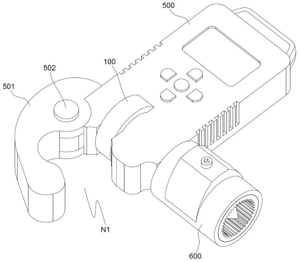
[0053] refer to Figure 1 to Figure 4 , this embodiment is different from the first embodiment in that: it also includes a housing 500, the diode 200, the alarm 300 and the power supply 900 are located in the housing 500, the display module 400 is located on the surface of the housing 500, and the contact 100 is located in the housing 500 outside;
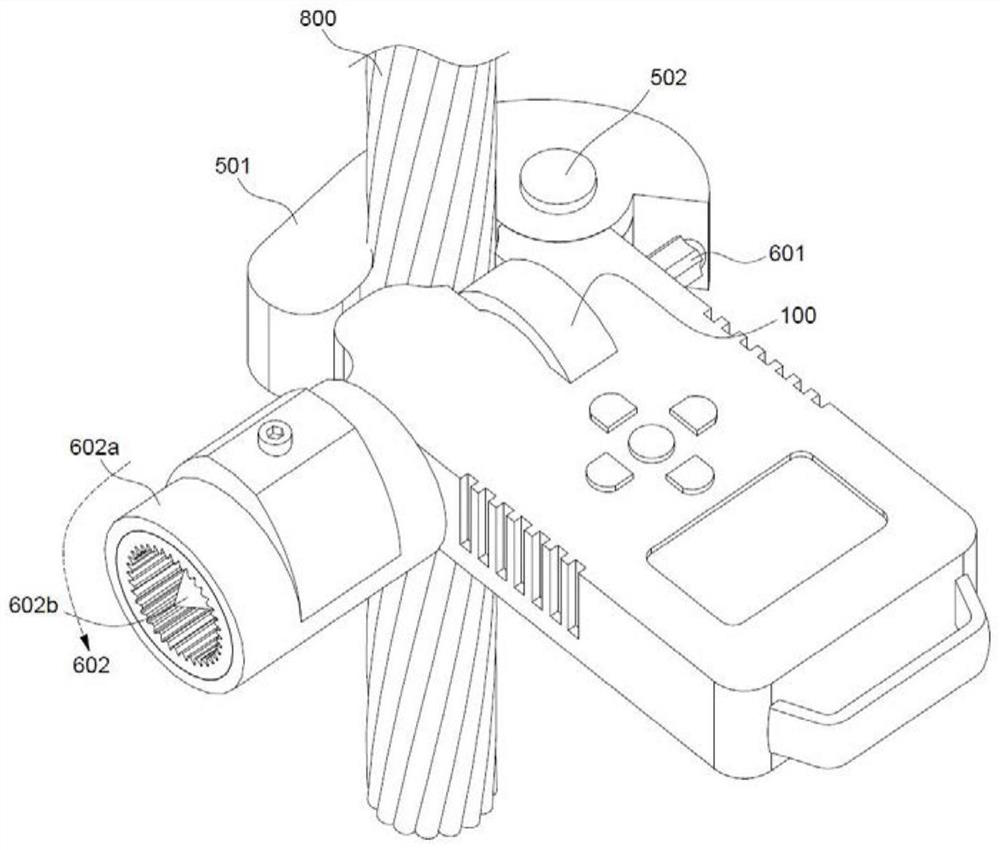
[0054] Wherein, the housing 500 is also provided with a locking member 501, the locking member 501 is hinged to the housing 500, an accommodating space N1 is formed between the locking member 501 and the housing 500, and the contact member 100 is located in the accommodating space N1; during detection, Place the distribution transformer grounding wire 800 in the accommodating space N1 and make contact with the contact piece 100. If the grounding wire 800 is electrified, use the unidirectional conductivity of the diode to introduce the alarm 300 and set the threshold value. The threshold is set to 36V. According to whether the grou...
Embodiment 3
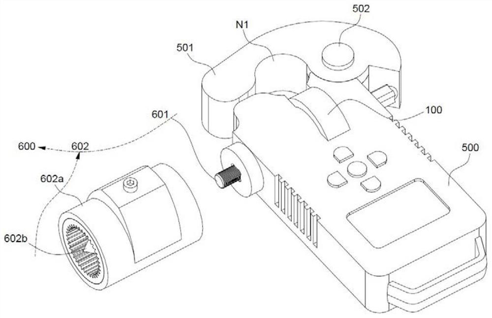
[0057] refer to Figure 3 to Figure 5 , this embodiment is different from the above embodiments in that: the middle part of the locking member 501 is rotatably connected with the housing 500 through the hinge shaft 502; wherein, the drive assembly 600 includes a push rod 601 and an operation assembly 602, and the operation assembly 602 can drive the push rod 601 Moving, the push rod 601 contacts one end of the locking member 501 and can push the locking member 501 to rotate around the hinge shaft 502 .
[0058] Specifically, the operating assembly 602 includes a support member 602a and a rotary member 602b, the support member 602a is connected to the housing 500, the rotary member 602b is rotationally connected to the support member 602a, and the push rod 601 is screwed to the rotary member 602b;
[0059] Wherein, the housing 500 is penetrated with a moving chamber N2 for accommodating the push rod 601, and the push rod 601 can only move linearly in the moving chamber N2; spec...
PUM
 Abstract
Description
Claims
Application Information
 - Generate Ideas
- Intellectual Property
- Life Sciences
- Materials
- Tech Scout
- Unparalleled Data Quality
- Higher Quality Content
- 60% Fewer Hallucinations
Browse by: Latest US Patents, China's latest patents, Technical Efficacy Thesaurus, Application Domain, Technology Topic, Popular Technical Reports.
© 2025 PatSnap. All rights reserved.Legal|Privacy policy|Modern Slavery Act Transparency Statement|Sitemap|About US| Contact US: help@patsnap.com