Eureka AIR delivers breakthrough ideas for toughest innovation challenges, trusted by R&D personnel around the world.

Inductive temperature measuring device and temperature measuring method, cooking device and electromagnetic device

A technology of temperature measuring device and electromagnetic device, which is applied in the fields of induction temperature measuring device, temperature measurement, cooking device and electromagnetic device, and can solve problems such as heat loss and inaccurate temperature measurement

Pending Publication Date: 2018-08-17
新兴县热点智能家居科技有限公司
View PDF0 Cites 3 Cited by
  • Summary
  • Abstract
  • Description
  • Claims
  • Application Information

AI Technical Summary

Problems solved by technology

The temperature measurement process is that the measured object transmits the temperature to the thermistor, the characteristics of the thermistor change, and the electrical signal of the thermistor is judged to detect the temperature. There is heat loss during the heat transfer process, and there is a certain hysteresis , so that the temperature measurement is not accurate enough

Method used


Image

  • Inductive temperature measuring device and temperature measuring method, cooking device and electromagnetic device
  • Inductive temperature measuring device and temperature measuring method, cooking device and electromagnetic device
  • Inductive temperature measuring device and temperature measuring method, cooking device and electromagnetic device

Examples


Embodiment 1

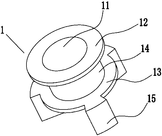
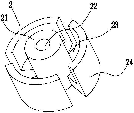
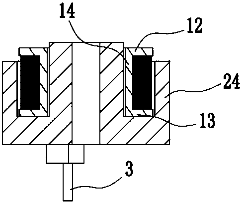
[0090] Such as figure 1 and as figure 2 As shown, the present invention provides an electromagnetic device, including a bracket 1 and a magnetic core 2, the bracket 1 is provided with a first spacer 12 and a second spacer 13, and the first spacer 12 and the second spacer 13 pass through Center column 14 is connected. An installation groove is formed between the first spacer 12 and the second spacer 13, and an electromagnetic coil is arranged on the installation groove.

[0091] The bracket 1 is provided with a mounting hole 11 , and the magnetic core 2 is provided with a magnetic core center post 21 , and the magnetic core center post 21 can fit into the mounting hole 11 to realize the connection between the support 1 and the magnetic core 2 . The magnetic core 2 is provided with a disk set connected to the central column 21 of the magnetic core. In this embodiment, the bottom magnetic disk 23 is connected with a magnetic tile 24, and the magnetic tile 24 is arranged perpen...

Embodiment 2

[0099] Such as Figure 5 , 6 As shown, in this embodiment, on the basis of Embodiment 1, a magnetic core cover 25 is added, and the magnetic core cover 25 is arranged on the top of the central column of the magnetic core. Preferably, the diameter of the magnetic core cover 25 is smaller than that of the bottom The diameter of the magnetic disk, the magnetic core cover plate 25 and the magnetic core center column can be integrally formed or detachably connected.

[0100] Preferably, the central column of the magnetic core is formed by the embedding of the first section 26 and the second section 27, and the first section 26 and the second section 27 are respectively provided with concavo-convex structures that can cooperate with each other, and the central column of the magnetic core is longitudinally , the concave-convex structure has an overlapping portion 28, and the height of the overlapping portion 28 is 0.03-3 mm. The concave-convex structure increases the contact area b...

Embodiment 3

[0102] Such as Figure 7 As shown, this patent also provides a cooking device, such as a gas stove, including a gas stove 5 and a cooking utensil 4 placed above the gas stove 5, the cooking utensil is preferably a pot 4, and the gas stove 5 includes a burner 51. Stove frame 52, panel 53, air intake pipe 55 and control valve 54. Panel 57 is provided with mounting holes. Burner head 51 is located in the installation hole. Stove frame 52 is located on panel 53. Stove frame 52 and burner head 51 Arranged in concentric circles, that is, the furnace frame 52 is arranged on the periphery of the furnace head 51 to support the object to be heated. The air inlet pipe 55 communicates with the furnace head 51 to provide a pipeline for gas supply. The air inlet pipe 55 is provided with a control valve 54, which can be a solenoid valve or other valves with the function of adjusting the gas flow. The induction temperature measuring device also includes an electromagnetic device 57 and a con...


PUM

PropertyMeasurementUnit
Thicknessaaaaaaaaaa
Heightaaaaaaaaaa
Heightaaaaaaaaaa

Abstract

The invention relates to an inductive temperature measuring device which is characterized in that the inductive temperature measuring device comprises an electromagnetic device capable of generating an electromagnetic signal and a control unit which is connected to the electromagnetic device and can detect electrical parameters in the electromagnetic device. The electromagnetic device comprises amagnetic core and an electromagnetic coil, the magnetic core includes a magnetic core middle pillar, the electromagnetic coil is arranged at the periphery of the magnetic core, the electromagnetic device can generate an electromagnetic signal after being energized, and the inductive temperature measuring device further comprises a temperature sensing layer capable of sensing the electromagnetic signal generated by the electromagnetic device. According to the inductive temperature measuring device, a traditional temperature measuring method is changed, the temperature of a temperature sensing layer is detected by the action of the electromagnetic signal, according to the detection method of the invention, the heat transfer between a tested object and the electromagnetic device is not needed, the temperature of the tested object can be directly tested without the loss of heat and without a heat transfer process, and the temperature measurement is more timely and more accurate.

Description

technical field [0001] The invention relates to an induction temperature measuring device and a temperature measuring method, and at the same time, the invention also relates to a cooking device and an electromagnetic device. Background technique [0002] Existing temperature measurement technology usually uses thermistors, which are a type of sensitive components. According to different temperature coefficients, they are divided into positive temperature coefficient thermistors (PTC) and negative temperature coefficient thermistors (NTC). . A typical feature of a thermistor is that it is sensitive to temperature and exhibits different resistance values ​​at different temperatures. A positive temperature coefficient thermistor (PTC) has a larger resistance value at higher temperatures, and a negative temperature coefficient thermistor (NTC) has a lower resistance value at higher temperatures. The temperature measurement process is that the measured object transmits the tem...

Claims


Application Information

Patent Timeline
IPC IPC(8): G01K7/36A47J27/00A47J27/08A47J36/02F24C3/12F24C7/08
CPCA47J27/002A47J27/08A47J36/02F24C3/126F24C7/082G01K7/36
Inventor 陈景超
Owner 新兴县热点智能家居科技有限公司
Why Eureka
Eureka Blog
Learn More