
Narrow-pulse high-current constant-current source and control method thereof

A control method and narrow pulse technology, applied in the direction of control/regulation system, regulation of electrical variables, instruments, etc., can solve problems such as difficult to increase signal rise and fall speed, difficult to reduce signal overshoot, etc., to achieve strong market application prospects , the effect of reducing heat

Pending Publication Date: 2021-03-12
北京麦特达电子技术开发有限公司
View PDF0 Cites 3 Cited by
  • Summary
  • Abstract
  • Description
  • Claims
  • Application Information

AI Technical Summary

Problems solved by technology

[0005] Aiming at the deficiencies of the prior art, the present invention discloses a narrow-pulse high-current constant-current source and its control method, which are used to solve the problem that the traditional design method is difficult to improve the signal due to the limitation of the slew rate of the digital-to-analog converter and the operational amplifier. Rise and fall speed, and it is not easy to reduce the problem of signal overshoot

Method used


Image

  • Narrow-pulse high-current constant-current source and control method thereof
  • Narrow-pulse high-current constant-current source and control method thereof
  • Narrow-pulse high-current constant-current source and control method thereof

Examples


Embodiment 1

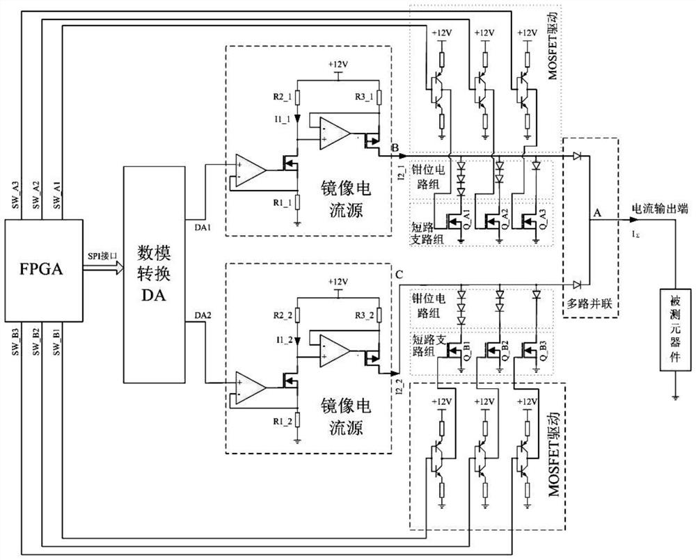
[0034] This embodiment discloses as figure 1 A narrow-pulse high-current constant-current source is shown, including a logic controller FPGA that drives the NMOS of the short-circuit branch through push-pull to increase the slope of the rising and falling edges of the pulse, and uses the SPI interface to connect the digital-to-analog converter DA to control the output voltage. After the mirror current source is op-amped, the current signal is output, and the MOSFET is driven to turn on or off the short-circuit branch through the multi-channel IO port. At the same time, the short-circuit branch is equipped with a clamp circuit to reduce the impact on the mirror current source. The overshoot of the narrow pulse; finally output the current to the component under test through multiple parallel connections.

[0035] In this embodiment, the FPGA adjusts the output voltage of the DA through the SPI interface, and also controls the driving of the MOSFET through multiple IO ports, so a...

Embodiment 2

[0041] This embodiment discloses a short-circuit branch. The traditional constant current source does not have a short-circuit branch. Therefore, the magnitude and pulse width of the current IΣ are usually controlled by analog quantities DA1 and DA2. However, the slew rate index of the digital-to-analog conversion module and the operational amplifier circuit The rising and falling process of the current I2_1 and I2_2 is limited, and it is difficult to realize a pulse width current of less than 1us.

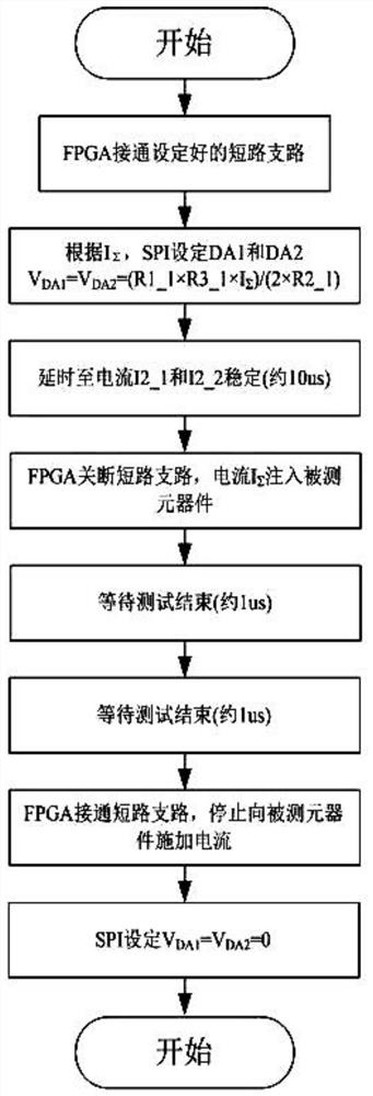
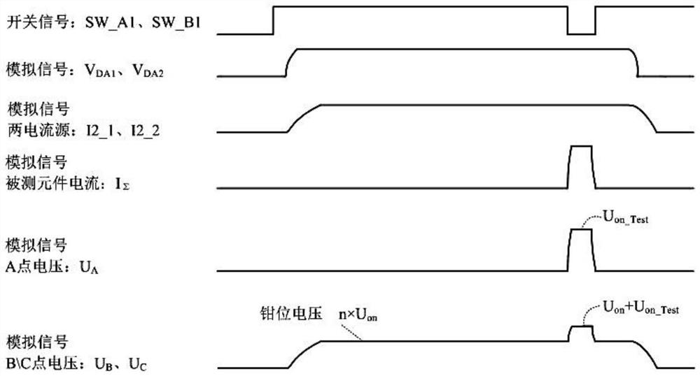
[0042] Further analysis shows that as long as the currents I2_1 and I2_2 change, the transition process will be subject to the slew rate of the operational amplifier in the current source, and an ideal transition process cannot be obtained. However, in the present invention, stable currents I2_1 and I2_2 have been obtained before the narrow pulse appears, and the two currents flow through the short-circuit branch, and the short-circuit branch is disconnected instantaneously to obta...

Embodiment 3

[0047] This embodiment discloses a clamping circuit, which is composed of multiple sets of diodes in series, and the conduction voltage of each diode is set as Uon, and each short-circuit branch group has an NMOS transistor connected to the clamping circuit to GND.

[0048] When the short-circuit branch is not conducting, the currents I2_1 and I2_2 are gathered to point A and pass through the component under test, so UB=Uon+Uon_Test. When the short-circuit branches Q_A1 and Q_B1 are turned on and satisfy Uon+Uon_Test>3Uon, the current I2_1 completely flows through the switch Q_A1, and the current I2_2 completely flows through the switch Q_B1, so UB=UC=3Uon, and UA=0V.

[0049] In this embodiment, the function of the clamping circuit group is that, as the aforementioned clamping circuit should satisfy n×Uon

[0...


PUM


Abstract

The invention relates to the technical field of semiconductor detection equipment, in particular to a narrow-pulse high-current constant-current source and a control method thereof. A logic controllerFPGA is arranged to drive NMOS of a short-circuit branch through push-pull driving to improve the slope of pulse rising and falling edges, an SPI interface is connected with a digital-to-analog converter DA to control the output voltage, a current signal is output through operational amplifiers of a mirror current source, an MOSFET driver is controlled through multiple IO ports to connect or disconnect the short-circuit branch, meanwhile, the short-circuit branch is provided with a clamping circuit in a matched manner, so that the impact on the mirror current source is reduced, the overshootof narrow pulses is reduced, and finally, the current is output to a tested component through multi-path parallel connection. According to the invention, the load current is dispersed to more components through parallel branches, so that the heating value of an MOSFET can be effectively reduced; and by arranging the short-circuit branch, the limitation of the slew rates of the operational amplifiers on the narrow pulse transition process is eliminated, and by arranging multiple paths of parallel circuits and a clamping circuit, narrow pulse large-current constant-current control of an approximate ideal waveform is realized.

Description

technical field [0001] The invention relates to the technical field of semiconductor detection equipment, in particular to a narrow-pulse high-current constant-current source and a control method thereof. Background technique [0002] In the testing process of semiconductor components, it is necessary to apply a momentary controllable large current between two pins to test the impact resistance of semiconductor components. Therefore, the detection equipment must provide a large current signal with a narrow pulse width, constant current and adjustable current. [0003] Therefore, the detection equipment should first have constant current characteristics and the current size is controlled by the program, secondly, it should be able to output a current signal with a narrow pulse width, and finally it should be able to provide a large current of several amperes or more. Due to the limitation of the slew rate of the digital-to-analog converter and the operational amplifier, the ...

Claims


Application Information

Patent Timeline
Patent Type & Authority Applications(China)
IPC IPC(8): G05F1/56G01R31/26
CPCG01R31/26G05F1/56
Inventor 申宇黄磊王文军
Owner 北京麦特达电子技术开发有限公司
Learn More