Motor positioning and stopping mechanism

A stopping mechanism and stopping technology, which is applied in the field of motor positioning and stopping mechanism, can solve the problems of rarely seen pure mechanical structure motors, the volume of the control mechanism increases, and the complex control mechanism, etc., and achieves a simple and compact overall structure and small internal space. , Universal effect

Active Publication Date: 2021-03-12
东莞市创龙电子有限公司
View PDF3 Cites 0 Cited by
  • Summary
  • Abstract
  • Description
  • Claims
  • Application Information

AI Technical Summary

Problems solved by technology

[0004] As we all know, the electrification of the mechanical part is a common method to reduce the volume of the traditional mechanical structure. If the electrical part of the existing servo motor PID control is changed to a purely mechanical structure, a very complicated control mechanism is required, and the volume of the control mechanism will definitely increase. , the cost is also very likely to increase. Based on the above reasons, it is rare to see a solution that relies on a purely mechanical structure to achieve motor positioning and stopping.

Method used


Image

  • Motor positioning and stopping mechanism
  • Motor positioning and stopping mechanism
  • Motor positioning and stopping mechanism

Examples


Embodiment 1

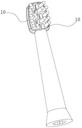
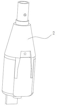
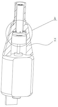
[0043] Such as Figure 1-6 As shown, in the motor positioning and stopping mechanism of this embodiment, the aforementioned inertial component 1 includes an inertia ring 1a sleeved on the power shaft, and a connecting through hole is opened on the inertia ring 1a, and a spiral shape is provided on the wall of the connecting through hole. The convex or concave structure is connected with the power shaft passing through the connection through hole through the spiral convex or concave structure. The movable ring 3a moving in the direction is provided with a stop structure on the movable ring 3a. After the motor is de-energized, the speed of the power shaft gradually decreases, and the inertia ring 1a rotates relative to the power shaft due to its own inertia, and rotates around the power shaft while moving along the axial direction of the power shaft under the action of the spiral protrusion or concave structure. Move towards the movable ring 3a, and the movable ring 3a is pushe...

Embodiment 2

[0049] Different from Example 1, see Figure 8-12 As shown, in this embodiment, the inertial component 1 includes an inertia ring 1a that is looped outside the power shaft, the movable part 3 includes a rotating bracket 3b and a brake pawl 3c provided with a stop structure, and the rotating bracket 3b is fixedly connected to the power shaft The brake pawl 3c is rotatably connected to one of the two parts of the inertia ring 1a and the rotating bracket 3b, and the remaining part is also connected to the brake pawl 3c and leaves a gap at the joint between it and the brake pawl 3c. quantity. When the motor is de-energized, the speed of the power shaft gradually decreases, and the aforementioned inertia ring 1a rotates relative to the power shaft due to its own inertia and pulls the brake claw 3c, prompting the brake claw 3c to rotate, so that the stop structure on the brake claw 3c Close to and abut against the stop structure on the immovable part 2, thereby preventing the power...

Embodiment 3

[0052] Similar to Embodiment 2, the inertial component 1 in this embodiment also includes an inertia ring 1a that is sheathed outside the power shaft, and the movable member 3 also includes a rotating bracket 3b and a brake pawl 3c provided with a stop structure, and the rotating bracket 3b The power shaft is also fixedly connected, and an accommodating cavity 3b1 is also provided in the rotating bracket 3b, and a gap 3b2 communicating with the accommodating cavity 3b1 is also provided on the side wall of the rotating bracket 3b, and the stop structure on the brake pawl 3c is also as follows: The front end of the arm claw, in addition, the fixed part 2 can also include a stationary ring 2a, and the stop structure on the fixed part 2 is also a protrusion 5 (of course, it can also be a groove) arranged on the stationary ring 2a. The difference between this embodiment and Embodiment 2 is that the inertia ring 1a is set in the accommodating cavity 3b1, the stationary ring 2a is set...


PUM


Abstract

The invention provides a motor positioning and stopping mechanism which comprises a brake assembly and an inertia part, the brake assembly comprises a fixed part and a movable part connected with thepower shaft, the fixed part and the movable part are provided with stop structures matched with each other, and the inertia part and the movable part are driven by the power shaft to rotate. The inertia part can rotate relative to the power shaft due to the inertia effect of the inertia part when the rotating speed of the power shaft changes. When the motor is powered off, the inertia part rotatesrelative to the power shaft due to the inertia effect of the inertia part, then the movable part is pushed or pulled, the stop structure of the movable part is made to be close to the stop structureof the fixed part, and the power shaft is prevented from rotating through the stop structures abutting against each other. The motor positioning and stopping mechanism can position and stop a power shaft for transmitting motor torque at a set position, adopts a pure mechanical structure as a whole, is free of any electrical element, simple and compact in structure, low in cost and high in universality, and is suitable for electric appliances which are small in internal space, high in rotating speed and inconvenient to control a travel switch and a servo motor.

Description

technical field [0001] The invention relates to the technical field of motor position control, in particular to a motor positioning stop mechanism. Background technique [0002] Many times we need the motor to be positioned and stopped at a certain position. For example, the electric double-headed roller toothbrush in the Chinese patent document CN110840612A requires that the two brush head bodies can be aligned together after the motor stops. If the two brush head bodies 10 are in the position after the motor stops figure 1 The position shown will make the gap between the bristle bundles in the middle of the brush head too large, and it is easy to squeeze the toothpaste into the above gap when using it next time, resulting in a decrease in user experience. [0003] Closed-loop control is a common way to achieve motor position control (including motor stop position control). The closed-loop control performs position correction according to the output feedback of the contro...

Claims


Application Information

Patent Timeline
Patent Type & Authority Applications(China)
IPC IPC(8): H02K7/102
CPCH02K7/102
Inventor 王众城
Owner 东莞市创龙电子有限公司
Why Eureka
Try Eureka