
Traction motor for train set

A technology for traction motors and EMUs, applied in the direction of electric components, electromechanical devices, electrical components, etc., can solve the problem that the ventilation structure is not suitable for intercity EMUs

Active Publication Date: 2022-03-11
CRRC YONGJI ELECTRIC CO LTD
View PDF5 Cites 1 Cited by
  • Summary
  • Abstract
  • Description
  • Claims
  • Application Information

AI Technical Summary

Problems solved by technology

[0006] The invention solves the problem that the ventilation structure of the existing self-ventilating traction motor is not suitable for intercity EMUs, and provides a traction motor for EMUs in order to adapt to the trend of extending the maintenance period of the EMU and reducing the maintenance cost

Method used


Image

  • Traction motor for train set
  • Traction motor for train set
  • Traction motor for train set

Examples


Embodiment Construction

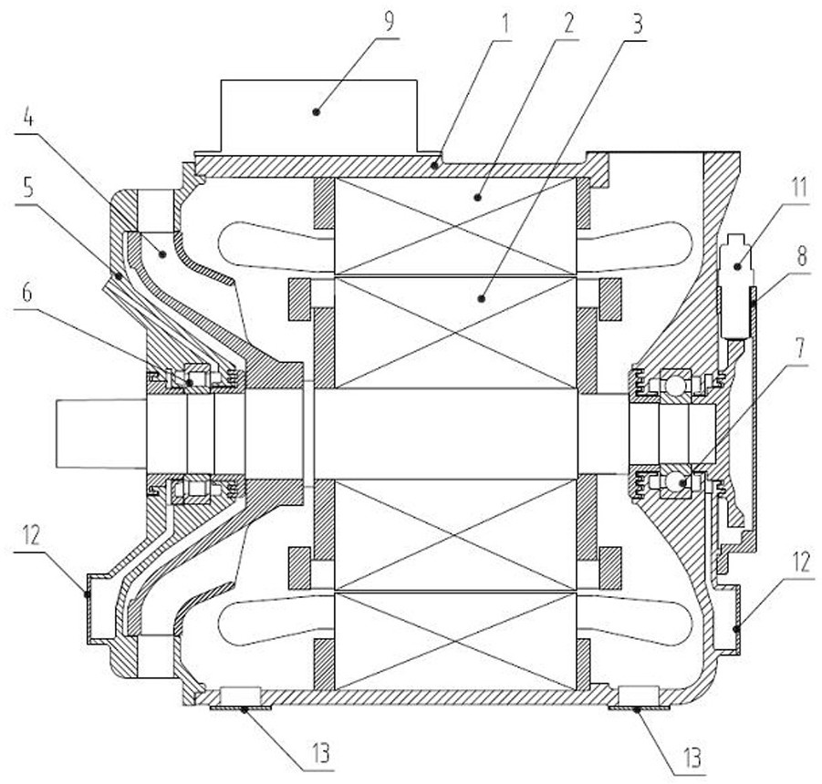
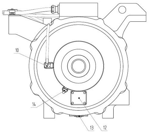
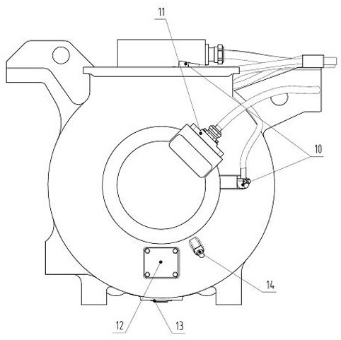
[0029] A traction motor for an EMU, comprising a barrel-shaped machine base 1 (that is, the transmission end of the machine base is open and the non-drive end is not open), the stator core 2 is shrink-fitted in the machine base 1, and the rotor 3 is installed on the rotor 3. The fan 4 at the transmission end of the shaft, and the end cover 5 at the transmission end; the air inlet is opened on the top of the non-transmission end of the frame 1, the air outlet is opened on the side of the end cover 5 of the transmission end, and the rotor 3 is punched with uniform holes in the circumferential direction of the core yoke. Ventilation holes in the cloth; the stator core 2 is punched with evenly distributed ventilation holes in the circumferential direction of the yoke. Such as Figure 4 As shown, the stator core 2 is shrunk into the base 1, and the top of the non-drive end of the base 1 is provided with an air inlet. The internal air path consists of three parts: stator core air p...


PUM


Abstract

The invention relates to a traction motor, in particular to a traction motor for an EMU. The invention solves the problem that the ventilation structure of the existing self-ventilating traction motor is not suitable for intercity EMUs. The utility model relates to a traction motor of an EMU, which has a three-channel ventilation structure. The motor adopts a split junction box, and the three-phase cable can be detached under the condition that the gland head is not required to be disassembled. Both ends of the motor are equipped with a large-capacity convex oil drain chamber, which can greatly improve the service life of the bearing under normal grease supply conditions. The non-drive end of the motor is equipped with a compact sensor bracket with a detection window, which is convenient for checking the installation gap between the sensor probe and the speed measuring gear. The sunken mounting hole is used, and the sunken protective cover plate is used to shorten the axial assembly size of the sensor bracket. , Increase the maintenance and operation space of the non-drive end of the motor. The bottom of the drive end and non-drive end of the machine base is equipped with dust removal holes and stepped protective cover plates to prevent water accumulation inside the motor and remove foreign objects inside the motor in time.

Description

technical field [0001] The invention relates to a traction motor, in particular to a traction motor for an EMU. Background technique [0002] Intercity EMU is a fast passenger rail transit mode between cities. The development space prospect of intercity EMU is getting wider and wider. [0003] Due to the structure of the intercity EMU, the line ramp and the quality limitations of the inverter power supply, it is determined that the traction motor must have the characteristics of high power density, high temperature rise margin, and easy maintenance. At present, the traction motors of intercity EMUs adopt two structural forms: forced ventilation and self-ventilation. Considering the advantages of small weight and simple structural arrangement, self-ventilated motors will become the mainstream direction in the future. Since the cooling effect of self-ventilated motors is worse than that of forced ventilation, the design of its ventilation structure is particularly important...

Claims


Application Information

Patent Timeline
Patent Type & Authority Patents(China)
IPC IPC(8): H02K9/06H02K1/20H02K1/32H02K5/04H02K5/10H02K5/16H02K5/20H02K5/22H02K11/21H02K11/25
CPCH02K9/06H02K1/20H02K1/32H02K5/225H02K5/04H02K5/10H02K5/20H02K5/161H02K11/21H02K11/25
Inventor 李广李世杰张婷赵宇坤郭岚岚
Owner CRRC YONGJI ELECTRIC CO LTD
Learn More