Local self-heating type condensation removing method for high-voltage switch cabinet

A high-voltage switchgear, self-heating technology, applied in the field of switchgear, can solve the problems of large damage to electrical components, short service life, damage to electrical components, etc., and achieve the effect of reducing condensation phenomenon and reducing the probability of damage

Active Publication Date: 2021-03-16
YULIN POWER SUPPLY BUREAU OF GUANGXI POWER GRID CO LTD
View PDF10 Cites 4 Cited by
  • Summary
  • Abstract
  • Description
  • Claims
  • Application Information

AI Technical Summary

Problems solved by technology

[0004] There are usually multiple electrical components installed in the switchgear, which will generate a lot of heat during operation. In winter, especially in areas with high air humidity, after being heated, the hot and humid air in the switchgear encounters the inner wall of the switchgear with a lower temperature. Due to the temperature difference, condensation will occur on the inner wall. When the condensation is severe, the condensed dew will drip on the electrical components in the switch cabinet, causing damage to the electrical components and short service life, especially on the top of the switch cabinet. When condensation occurs at this place, the condensed water drops will fall vertically and will fall directly on the electrical components. Compared with the condensation on the side wall, the condensation at this place will do more damage to the electrical components

Method used


Image

  • Local self-heating type condensation removing method for high-voltage switch cabinet
  • Local self-heating type condensation removing method for high-voltage switch cabinet
  • Local self-heating type condensation removing method for high-voltage switch cabinet

Examples


Embodiment 1

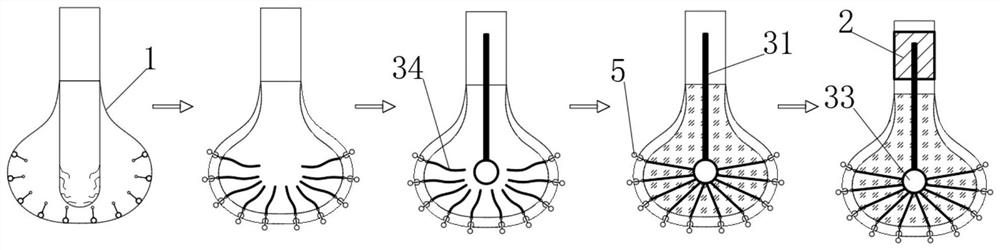
[0044] see figure 1 , a local self-heating high-voltage switchgear decondensation method, comprising the following steps:

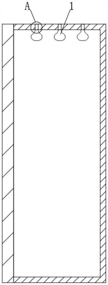
[0045] S1. When the temperature is low in winter, first fill the multiple double-layer self-heating bags 1 with high-temperature inert gas, so that the inner layer and the outer layer are squeezed;

[0046] S2. Under the extrusion effect of the inner layer, the moisture-absorbing self-heating rod is extruded to the outside of the double-layer self-heating bag;

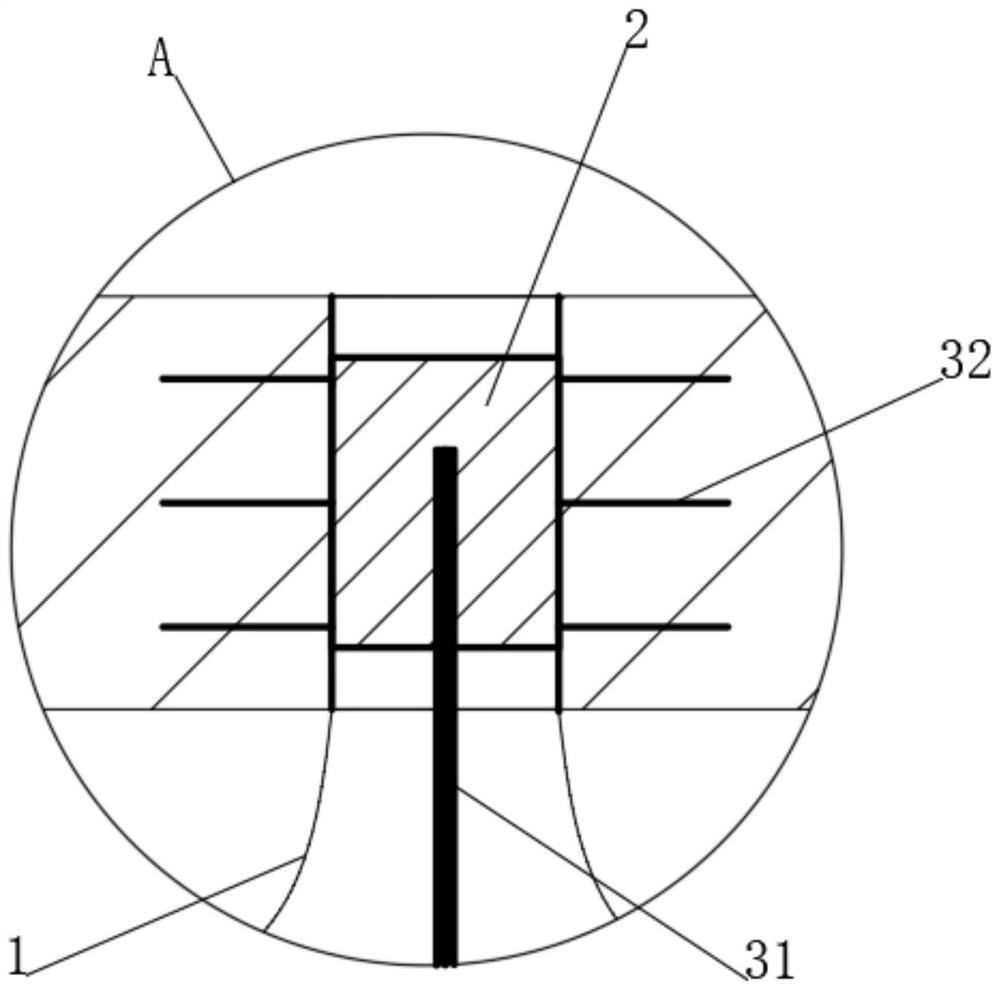
[0047] S3, then inserting the heat-conducting main rod 31 into the inner layer of the double-layer self-heating bag, and filling the interior with heat-storing particles, so as to shape the inner layer of the double-layer self-heating bag;

[0048] S4. Insert the heat conduction block 2 at the mouth of the double-layer self-heating bag, and the heat conduction block 2 is in close contact with the inside of the heat conduction hole on the top of the switch cabinet;

[0049] S5. The end of the moi...


PUM


Abstract

The invention discloses a local self-heating type high-voltage switch cabinet condensation removing method, and belongs to the field of switch cabinets. The local self-heating type high-voltage switchcabinet condensation removing method comprises the steps that a double-layer self-heating bag is arranged at the top of a switch cabinet, and when the temperature in winter is low, the double-layer self-heating bag absorbs water vapor in the switch cabinet, heat can be generated spontaneously; and on one hand, heat is concentrated inside through heat storage particles and transferred to the top of the switch cabinet through a heat conduction main rod, a heat conduction blocking block and heat conduction branch rods, so that the effect of adsorbing moisture and reducing the occurrence rate ofcondensation can be achieved, and on the other hand, relatively high heat at the top of the switch cabinet can be kept, and therefore, the condensation phenomenon of wet hot air in the switch cabinetcan be effectively removed. Compared with the prior art, the situation that condensed water drops directly and vertically fall off from the top of the switch cabinet can be effectively avoided, and then the probability that electrical elements in the switch cabinet are damaged due to the fact that electrical elements make contact with water is remarkably reduced.

Description

technical field [0001] The invention relates to the field of switch cabinets, and more specifically, relates to a method for removing condensation in a local self-heating high-voltage switch cabinet. Background technique [0002] The switch cabinet is a kind of electrical equipment. The external line of the switch cabinet first enters the main control switch in the cabinet, and then enters the sub-control switch, and each branch is set according to its needs. Such as instruments, automatic controls, motor magnetic switches, various AC contactors, etc., some also have high-voltage room and low-voltage room switch cabinets, high-voltage busbars, such as power plants, etc. load shedding. [0003] The main function of switchgear is to switch, control and protect electrical equipment during the process of power generation, transmission, distribution and power conversion in the power system. The components in the switch cabinet are mainly composed of circuit breakers, disconnect...

Claims


Application Information

Patent Timeline
Patent Type & Authority Applications(China)
IPC IPC(8): B01D53/26
CPCB01D53/261
Inventor 蔡壮
Owner YULIN POWER SUPPLY BUREAU OF GUANGXI POWER GRID CO LTD
Why Eureka
Try Eureka