
Sunglasses lens coating equipment

A coating equipment and lens technology, applied in sputtering coating, vacuum evaporation coating, ion implantation coating, etc., can solve the problems of time-consuming vacuuming and energy consumption, long time required for coating, lack of buffer mechanism, etc. Improve work efficiency, reduce the number of repeated vacuuming and vacuuming, and reduce the effect of heating time

Active Publication Date: 2021-03-16
DONGXING HUAHONG OPTICAL TECH
View PDF12 Cites 2 Cited by
  • Summary
  • Abstract
  • Description
  • Claims
  • Application Information

AI Technical Summary

Problems solved by technology

The above-mentioned coating equipment has the following problems: every time the coating is completed, the coating space must be evacuated once, the steps are complicated, time-consuming, and the vacuuming energy consumption is high, so the production efficiency is low; the substrate can only be processed after it is loaded into the coating space. Procedures such as preheating and heating lead to a longer time required for coating a single substrate and lower production efficiency; the substrate is coated under a certain temperature in a vacuum, and due to the lack of a buffer mechanism, the film layer will withstand a certain amount of pressure after changes in temperature and air pressure. Defects due to stress

Method used


Image

  • Sunglasses lens coating equipment
  • Sunglasses lens coating equipment
  • Sunglasses lens coating equipment

Examples


Embodiment Construction

[0049] The present invention will be further described in detail below in conjunction with the embodiments, so that those skilled in the art can implement it with reference to the description.

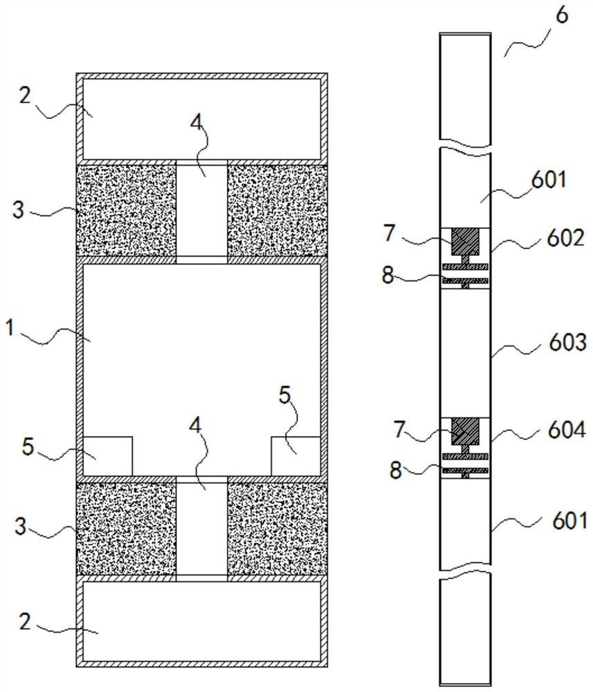
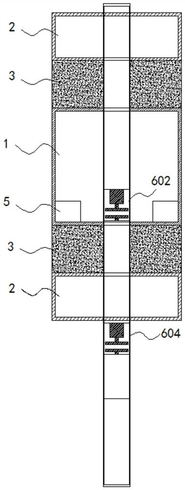
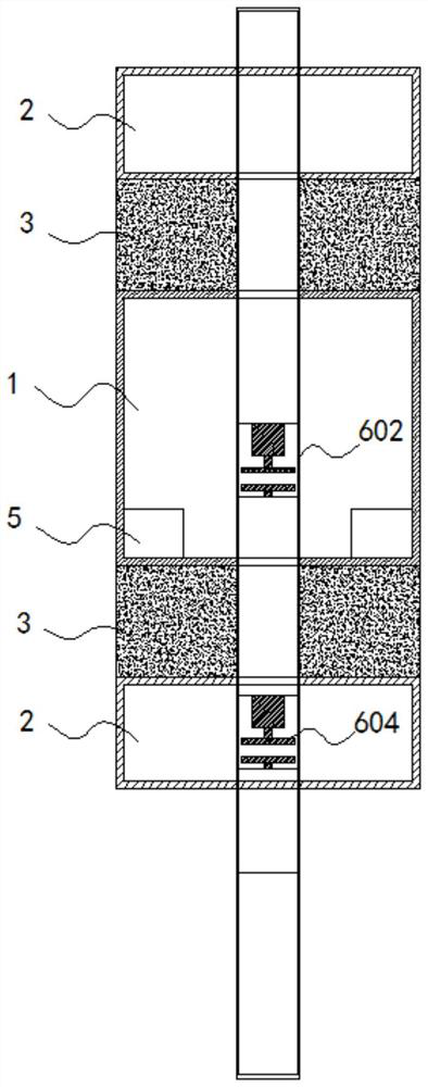
[0050] Such as figure 1 As shown, a sun lens coating equipment includes a coating chamber 1, a vacuum system, a heating system, a film material excitation system 5 and a film thickness control system 8; the vacuum system is generally composed of a vacuum pump, a sensor and a controller, and is used to control each The vacuum degree of the cavity; the heating system consists of a heating module, a sensor and a controller, and the heating module can be a heating wire or an infrared heater; among them:

[0051] On opposite sides of the coating chamber 1 ( figure 1 The upper and lower sides) are respectively provided with a buffer chamber 2, the buffer chamber 2 includes a first buffer chamber and a second buffer chamber, the first buffer chamber and the second buffer chamber are symmetri...


PUM


Abstract

The invention discloses sunglass lens coating equipment. The sunglass lens coating equipment comprises a coating cavity, a vacuum system, a heating system, film material excitation systems, film layerthickness control systems and axis components, wherein buffer cavities are formed in the two side parts of the coating cavity correspondingly, and shuttling channels penetrate through separation parts and the buffer cavities; the axis components are arranged in the shuttling channels in a sleeved mode, and the axis components are sequentially provided with sealing sections, first mounting sections, middle sections, second mounting sections and sealing sections; and substrates are arranged on the mounting sections, the relative position relation of two mounting sections is utilized, and different processes can be complete on two substrates at the same time in the same time period and do not conflict with each other. According to the sunglass lens coating equipment, the space utilization rate of the coating cavity is effectively improved, and the repeated vacuumizing and vacuum losing times of the coating cavity are reduced; and the design of the buffer cavities ensures that the substrates are subjected to pretreatment and annealing treatment processes, so that the time required for heating the substrates in the coating cavity is shortened, and the risk of defects caused by severe environmental change after the substrates are withdrawn from the coating cavity after the coating operation is completed is reduced.

Description

technical field [0001] The invention relates to the technical field of lens coating equipment, and more specifically, the invention relates to a sun lens coating equipment. Background technique [0002] Glass lenses have excellent light transmittance, no aging, high temperature resistance technology and excellent double-sided coating performance, etc., and have been used in high-end sunglasses. Glass lenses after tempering treatment have good anti-drop and anti-abrasion properties, and glass lenses account for a large proportion of foreign high-end sunglasses. Sunglasses based on tempered glass lenses include polarized lenses, gradient lenses, bright film lenses and colorful composite lenses, etc., and coating technology is a very important part of sunglass production. [0003] The coating of the lens needs to be carried out in the coating equipment. The existing coating equipment has a vacuum system, a heating system, a film material emission system and a film thickness co...

Claims


Application Information

Patent Timeline
Patent Type & Authority Applications(China)
IPC IPC(8): C23C14/50C23C14/02C23C14/56C23C14/58G02B1/14
CPCC23C14/505C23C14/02C23C14/568C23C14/5806G02B1/14
Inventor 刘德兴
Owner DONGXING HUAHONG OPTICAL TECH
Learn More