Water-rich sand layer shield interval contact channel stratum pre-reinforcement structure and method

A technology of communication channel and water-rich sand layer, which is applied in the direction of tunnel, earthwork drilling, tunnel lining, etc., can solve the problems that the construction period cannot be effectively guaranteed, safety accidents are prone to occur, and construction safety risks are large, so as to ensure the quality of reinforcement And connection effect, enhanced reinforcement effect, good effect of reinforcement effect

Active Publication Date: 2021-03-16
中铁二十局集团第五工程有限公司
View PDF5 Cites 1 Cited by
  • Summary
  • Abstract
  • Description
  • Claims
  • Application Information

AI Technical Summary

Problems solved by technology

However, for water-rich sand layer areas, due to the loose sand and gravel structure, large porosity, poor self-stability of the ground, and high excavation risks, how to ensure the construction quality and safety of communication channels has become an urgent problem to be solved
At present, the conventional construction scheme adopted for underground excavation of connecting passages in subway intervals in water-rich sand layers not only has a long period, but also has a serious impact on the construction of other processes. The most important thing is that construction safety risks are relatively high, and safety accidents are extremely prone
In terms of ground reinforcement, jet grouting piles are now mainly used for reinforcement. During the reinforcement process of jet grouting piles, not only has a great impact on the ground, but also when the communication channel is buried deep, the construction is difficult and the investment cost is high, and the construction period cannot be effectively guaranteed.
[0003]

Method used


Image

  • Water-rich sand layer shield interval contact channel stratum pre-reinforcement structure and method
  • Water-rich sand layer shield interval contact channel stratum pre-reinforcement structure and method
  • Water-rich sand layer shield interval contact channel stratum pre-reinforcement structure and method

Examples


Embodiment Construction

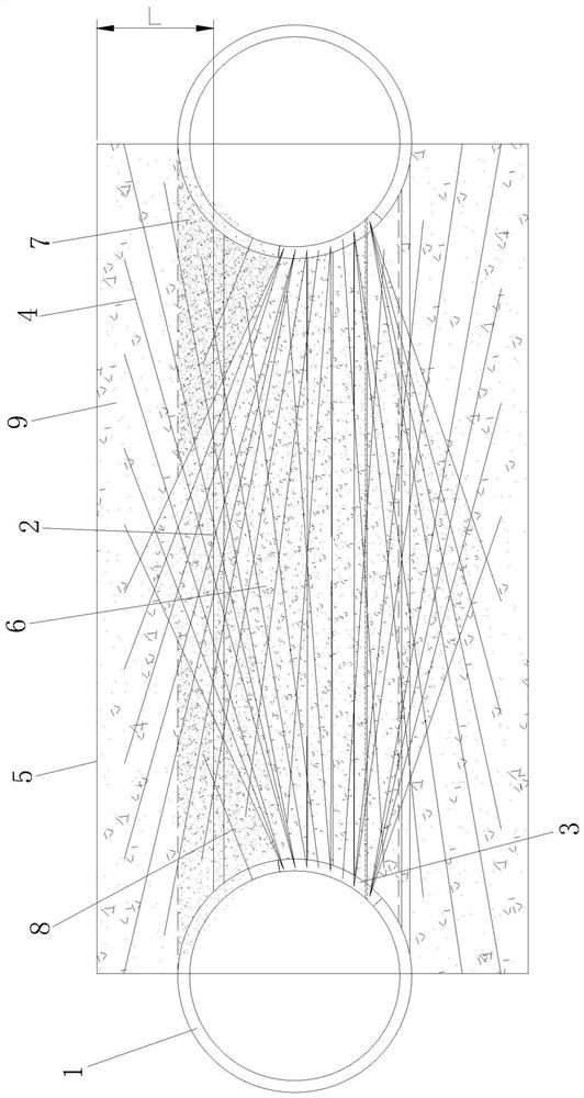
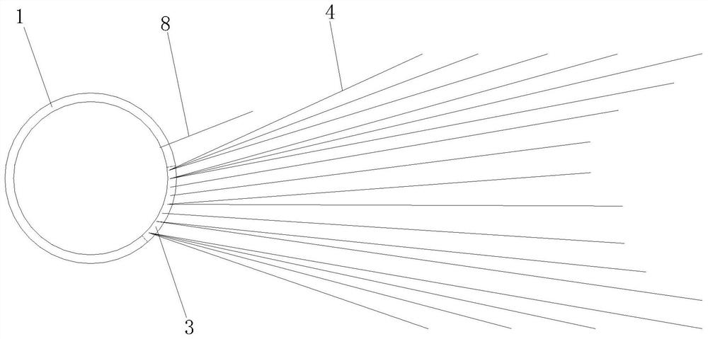
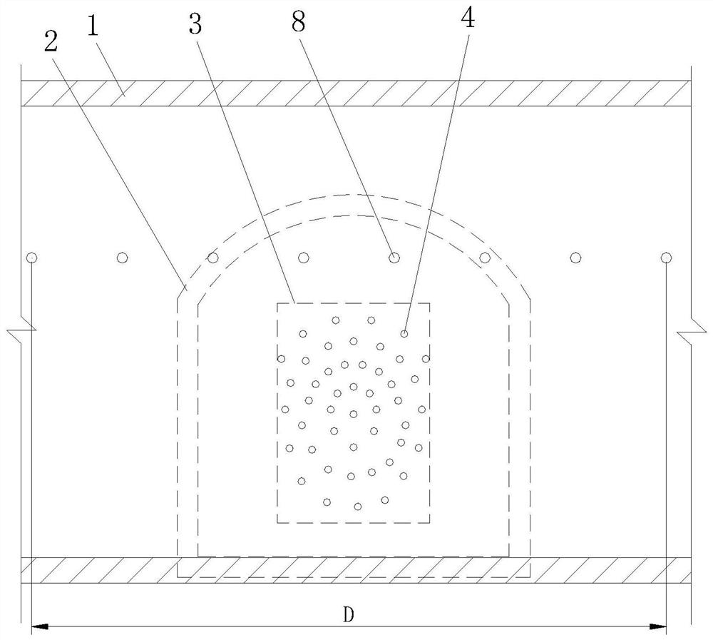
[0052] like Figure 1 to Figure 3 The shown pre-strengthening structure of the connection channel stratum in the shield tunnel interval of the water-rich sand layer includes an overall reinforcement structure of the channel stratum for reinforcing the stratum in the area where the communication channel 2 is constructed, and two front and rear sections of the communication channel 2 to be constructed, respectively. The channel end stratum reinforcement structure is reinforced by the end stratum, and the two channel end stratum reinforcement structures are respectively located on the front and rear sides of the channel stratum integral reinforcement structure, and both of them are fastened and connected to the channel stratum integral reinforcement structure as follows: One body; the constructed communication channel 2 is an undercut tunnel connected between the two shield tunnels 1 and the tunnel body is located in the water-rich sand layer;

[0053] The ground reinforcement st...


PUM


Abstract

The invention discloses a water-rich sand layer shield interval contact channel stratum pre-reinforcement structure and method. The pre-reinforcing structure comprises a channel stratum overall reinforcing structure for reinforcing the stratum of the area where a constructed connection channel is located and two channel end portion stratum reinforcing structures for reinforcing the stratum of thefront end and the stratum of the rear end of the constructed connection channel. The method comprises the following steps of 1, arranging advanced small conduits; 2, grouting and reinforcing the stratum at the end parts of the channel; and 3, integrally grouting and reinforcing the channel stratum. The pre-reinforcing structure is reasonable in design, easy and convenient to construct and good inreinforcing effect, the advanced to-be-reinforced area of the water-rich sand layer contact channel stratum is divided, the grouting reinforcing structure of the corresponding type is adopted for effective reinforcing, the reinforced stratum and a shield segment of the constructed shield tunnel are fixedly connected into a whole, and the structural stability of the shield tunnel can be effectivelyimproved while the stratum reinforcing effect of the constructed connection channel is further improved.

Description

technical field [0001] The invention belongs to the technical field of connection channel construction in shield tunnel sections, and in particular relates to a stratum pre-reinforcement structure and method for a shield tunnel section with a water-rich sand layer. Background technique [0002] In subway tunnel construction, for emergency evacuation and drainage needs, it is necessary to set up a communication channel in the shield tunnel section. The construction risk of the communication channel is relatively high, and it has always been an accident-prone part in subway construction. Accidents in the communication channel can easily lead to the damage of ground cables and buildings, and even endanger the entire subway line. Therefore, the communication channel construction plays a pivotal role in the shield construction. However, for the water-rich sand layer area, due to the loose sand and gravel structure, large void ratio, poor stratum self-stability, and high excavat...

Claims


Application Information

Patent Timeline
IPC IPC(8): E21D11/00E21D11/08E21D11/10E21D9/00
CPCE21D11/003E21D11/08E21D11/105E21D9/001Y02E10/20
Inventor 唐喜奎魏辉李朝成朱旬张群利翟晓飞张焱王旭王豆杰曲业坤
Owner 中铁二十局集团第五工程有限公司
Why Eureka
Try Eureka