Water-rich sand layer shield tunnel construction method

A technology of shield tunneling and water-rich sand layers, which is applied in tunnels, tunnel linings, earthwork drilling and mining, etc., can solve the problems of poor self-stability, low bearing capacity, sand collapse and other problems, and achieves simple steps and low manpower and material resources. The effect of less and high construction efficiency

Active Publication Date: 2021-03-16
CHINA RAILWAY 20 BUREAU GRP
View PDF6 Cites 2 Cited by
  • Summary
  • Abstract
  • Description
  • Claims
  • Application Information

AI Technical Summary

Problems solved by technology

Especially when constructing tunnels in water-rich sand layers with strong water-richness, loose structure, and poor bonding ability, the tunnel construction area during tunnel shield machine excavation belongs to the strong influence area on buildings and viaducts, and the compression of water-rich sand layers In the process of shield machine excavation, it is very easy to induce disaster accidents such as shield tunnel sand collapse, which seriously threatens the safety of tunnel excavation, and the soil caused by shield machine excavation The body disturbance generates pressure on the surrounding strata, and the pressure is transmitted to the surroundings. The conduction speed is fast and the conduction range is wide. When the cutterhead of the shield machine rotates and cuts, it is easy to destroy the original relatively stable or balanced state of the stratum, causing the shield machine to fall. And the excessive lateral force on the pile foundation of the existing viaduct will endanger the safety of the shield machine and the existing viaduct

Method used


Image

  • Water-rich sand layer shield tunnel construction method
  • Water-rich sand layer shield tunnel construction method
  • Water-rich sand layer shield tunnel construction method

Examples


Embodiment Construction

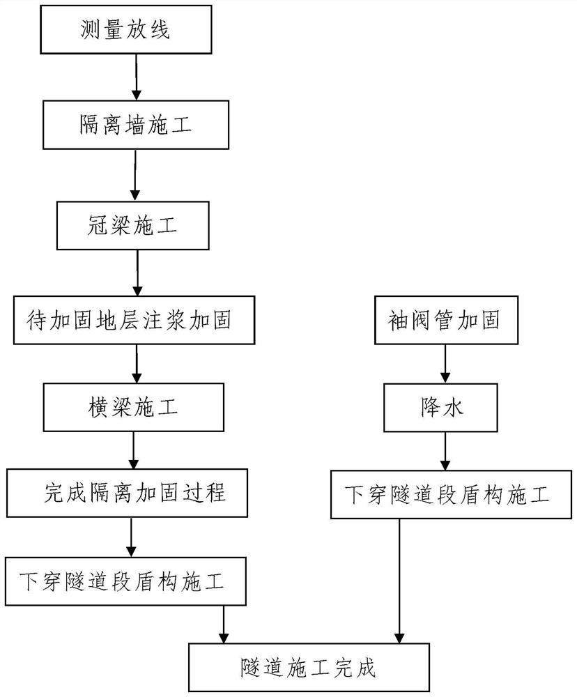
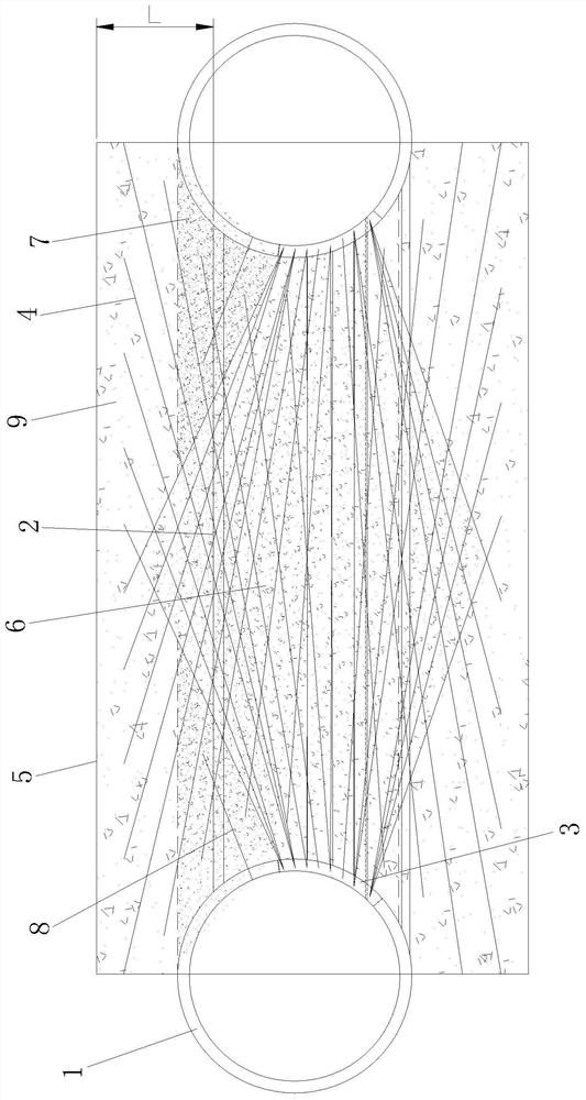
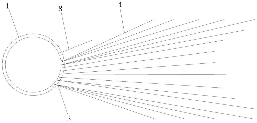
[0081] Such as figure 1 The construction method of a shield tunnel in a water-rich sand layer is shown. The tunnel to be constructed is a double-cavity tunnel and it is an underground excavation tunnel whose body is located in a water-rich sand layer. The two tunnel holes of the constructed tunnel are both shield tunnels. Tunnel 1; the constructed tunnel includes an underpassing viaduct tunnel section and a non-underpassing viaduct tunnel section connected with the underpassing viaduct tunnel section, a tunnel hole of the underpassing viaduct tunnel section passes through an existing viaduct and the tunnel hole In order to pass under the tunnel section, the two tunnel holes of the non-underpassed viaduct tunnel section are connected through the connecting passage 2, see figure 2 ;

[0082] When constructing the constructed tunnel, the two tunnel holes of the underpassed viaduct tunnel section and the two tunnel holes of the non-underpassed viaduct tunnel section are construc...


PUM


Abstract

The invention discloses a water-rich sand layer shield tunnel construction method. A constructed tunnel is a double-hole tunnel and is a subsurface tunnel with a hole body located in a water-rich sandlayer, the constructed tunnel comprises an underneath pass tunnel section passing through an existing viaduct and three non-underneath pass tunnel sections, shield construction is performed after theunderneath pass tunnel section is isolated and reinforced, and precipitation is not needed. The shield construction is conducted after precipitation of the non-underneath pass tunnel sections. The method is reasonable in design, easy and convenient to construct and good in using effect, a shield tunnel is divided into the underneath pass tunnel section and the non-underneath pass tunnel sectionsaccording to whether the viaduct is underneath pass or not, and construction is directly conducted after the non-underneath pass tunnel sections are subjected to precipitation. The underneath pass tunnel section is isolated and reinforced to form a slurry consolidated body, so that a shield tunneling machine performs tunneling construction in the slurry consolidated body, and soil disturbance andformation pressure caused by tunneling of the shield tunneling machine during construction are resisted through the slurry consolidated body. Separation walls are arranged on the two sides of the slurry consolidated body respectively, the formation pressure can be completely blocked, and safety and zero settlement of the viaduct on the upper side of the underneath pass tunnel section are guaranteed.

Description

technical field [0001] The invention belongs to the technical field of shield tunnel construction, and in particular relates to a construction method of a shield tunnel in a water-rich sand layer. Background technique [0002] With the large-scale construction of urban rail transit in my country, the utilization rate of urban underground space is gradually increasing, and urban subways inevitably pass under existing buildings or viaduct foundations, which will inevitably bring about the protection of these existing buildings and viaduct foundations with reinforcement puzzles. Especially when constructing a tunnel in a water-rich sand layer with strong water-richness, loose structure, and poor bonding ability, the tunnel construction area during the excavation of the tunnel shield machine belongs to the strong influence area on buildings and viaducts, and the compression of the water-rich sand layer In the process of shield machine excavation, it is very easy to induce disast...

Claims


Application Information

Patent Timeline
Patent Type & Authority Applications(China)
IPC IPC(8): E21D11/00E21D11/10E21D9/00E21D11/08
CPCE21D11/003E21D11/105E21D9/001E21D11/08Y02E10/20
Inventor 谢江胜任少强樊小林杨星智王存宝
Owner CHINA RAILWAY 20 BUREAU GRP
Why Eureka
Try Eureka