Multi-stage temperature detection circuit and temperature detection method

A temperature detection circuit, multi-stage technology, applied in thermometers, thermometers with directly sensitive electrical/magnetic components, measuring devices, etc., to achieve the effect of simplified structure, low power consumption design, and improved integration.

Active Publication Date: 2021-03-16
上海摩芯半导体技术有限公司
View PDF6 Cites 2 Cited by
  • Summary
  • Abstract
  • Description
  • Claims
  • Application Information

AI Technical Summary

Problems solved by technology

[0031] The purpose of the present invention is to solve the problem that the existing multi-section temperature detection circuit needs to set multiple thermistors RTC and multiple comparators when collecting multiple temperature points To solve the problem, a multi-stage temperature detection circuit and temperature detection method are provided. Only one thermistor RTC and two comparators are set to realize multi-stage temperature detection.

Method used


Image

  • Multi-stage temperature detection circuit and temperature detection method
  • Multi-stage temperature detection circuit and temperature detection method
  • Multi-stage temperature detection circuit and temperature detection method

Examples


Embodiment 1

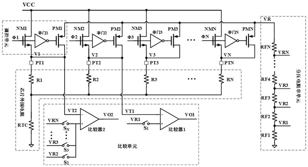
[0060] Such as figure 2 As shown in the present embodiment, the multi-stage temperature detecting circuit includes an internal circuit and a peripheral circuit, and the internal circuit is integrated into the integrated circuit of the control chip, and the internal circuit includes n NMOS tube: Nm1-NMN, N PMOS tube: PM1-PMN, N non-door: Non-door 1-non-door N, sequentially connected N RF resistance: RF1-RFN, 2 comparators: comparator 1 and comparator 2, where N is Gady greater than or equal to 2; the peripheral circuit includes a resistor R1-Rn and a thermistor RTC, and the threshold value of each temperature point can be adjusted by independently adjusting the resistance of the partial voltage resistor in series.

[0061] Specifically, the gate ends of the N NMOS tube NM1-NMN are connected to the gate control signal φ1-φn, respectively, and are connected to the input of the non-door 1-non-gate N; NMOS tube NM1-NMN, the drain end and join To the power supply VCC terminal; the sour...

Embodiment 2

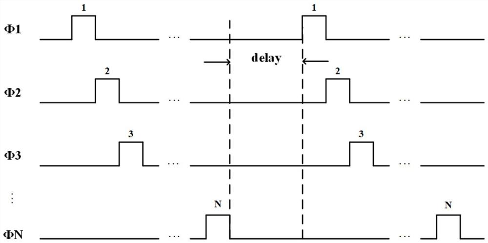
[0066] Combine figure 2 3, the VCC provides power supply for the chip, and the specific operation of the multi-stage temperature detecting circuit of the present embodiment is as follows:

[0067] When the gate control signal φ1 is high, the remaining gate control signal φi other than φ1 is low, the NMOS tube Nm1 is turned on, and the high-level gate control signal φ1 passes through the non-door 1 to low power. Flat, the PMOS pipe PM1 is turned on, and the gate control signal φ1 is turned on the switch S1, and the switch S1 is closed when the switch S1 is high. The source voltage of the NMOS tube NM1 is a voltage value after the gate control signal φ1 is high, that is, the voltage V1, and the source drain voltage of the PMOS pipe PM1, that is, VR = V1. After the voltage Vr is resistant to the resistor network, according to the series resistance division pressure, the voltage value of the positive phase input end of the comparator 1 can be obtained:

[0068]

[0069] That is, th...


PUM


Abstract

The invention relates to the technical field of temperature detection, in particular to a multi-section temperature detection circuit and a temperature detection method. The multi-section temperaturedetection circuit comprises at least two regulation and control units, a comparison unit and a divider resistor string unit. The comparison unit comprises two comparators, the positive-phase input ends of the two comparators are respectively connected to the divider resistor string unit to obtain a divided voltage value, the negative-phase input ends of the two comparators are respectively connected with the two regulation and control units, and the regulation and control units are used for regulating the voltage values of the positive-phase input ends of the two comparators. According to theinvention, the use of a thermistor RTC and a comparator can be reduced, and only one thermistor RTC and two comparators are used, so that the application cost is reduced, the PCB area is reduced, thenumber of pins of an acquisition chip is reduced, and the complexity of an application circuit is reduced; and N switches and N gate end control signals are introduced, the gate end control signals serve as on-off control signals of switches at the same time, the power consumption of the acquisition circuit can be reduced by controlling the acquisition period, and low power consumption is achieved.

Description

Technical field [0001] The present invention relates to the field of temperature detection, and in particular, a multi-stage temperature detecting circuit and a temperature detection method. Background technique [0002] The temperature detection circuit is an important part of some electronic systems. In practical applications, temperature detecting techniques can detect the temperature of the PCB board, the temperature of the battery, the electronic component, and the temperature of the chip. Temperature detection technology is also an important part in technology, and temperature detection techniques. [0003] The thermistor is a temperature-sensitive electronic component, which behaves different at different temperatures as different resistance values. According to the temperature coefficient, the thermistor is divided into two categories of positive temperature coefficient thermistor (PTC) and negative temperature coefficient thermistor (NTC). The greater the resistance valu...

Claims


Application Information

Patent Timeline
Patent Type & Authority Applications(China)
IPC IPC(8): G01K7/24
CPCG01K7/24
Inventor 张吉儒叶兆屏
Owner 上海摩芯半导体技术有限公司
Why Eureka
Try Eureka