
Wafer defect detection system and method

A defect detection and wafer technology, applied in optical testing flaws/defects, measuring devices, material analysis by optical means, etc., can solve problems such as difficult rotation control, difficulty in debugging, inability to meet detection speed, detection accuracy, etc.

Pending Publication Date: 2021-03-16
ZHEJIANG LAB +2
View PDF4 Cites 14 Cited by
  • Summary
  • Abstract
  • Description
  • Claims
  • Application Information

AI Technical Summary

Problems solved by technology

[0002] Wafer defect detection refers to detecting whether there are grooves, particles, scratches and other defects in the wafer and recording the defect position and quantity. Wafer defect detection is widely used and is a key link in semiconductor processing. Manual detection is the product surface defect detection However, with the development and progress of society, the traditional detection methods can no longer meet the requirements of detection speed and detection accuracy. With the development of industrial automation, defect detection equipment based on machine vision technology can be used, and defect detection equipment detection High consistency and high accuracy can greatly reduce the cost of employment, which is the trend of wafer defect detection in the future;
[0003] Conventionally, there is a rotating wafer detection method for the detection of the wafer surface, which is implemented by moving the optical detection system from the edge to the center of the circle along the radial direction of the wafer while the wafer is rotating at a high speed, and the detection trajectory is a spiral, as disclosed in The patent document No. US6201601B1 discloses a wafer detection method that uses a rotating wafer method and uses a point confocal optical system to improve the resolution. The rotating wafer detection method is detected at the same angular velocity because the distance from the detected position to the center of the circle is different. There is a difference in position and linear velocity, which can easily cause the problem of unbalanced sampling. Therefore, the rotary table is required to control the variable speed rotation of the wafer. At the same time, this patent uses single-point scanning, and the detection speed is relatively slow. The patent document with the publication number CN110849899 A discloses a A defect detection system based on line confocal, which scans the line spot, rotates the stage, and uses multiple angle detectors to receive the surface defect detection device for scattering signals; the patent document with the publication number US6858859 proposes a diffraction element based Diffraction multiple light spots irradiate the surface of the sample. The imaging path of each light spot is a confocal illumination system. By rotating the stage, multi-beam spot scanning, and a surface defect detection device that receives scattering signals with a single objective lens, although the two Compared with single-point confocal detection, this patent can improve detection efficiency, but the rotating wafer detection method requires variable speed rotation of the stage, and the problem of high synchronization of multiple sets of signals has not been fundamentally solved, resulting in complicated control circuits. difficult to debug;
[0004] Another detection method of the wafer surface is a line-by-line uniform-speed scanning detection method. For example, the patent document with the publication number US9551672B2 combines area array imaging and linear array imaging, and avoids the above-mentioned difficult problem of rotation control by means of line-by-line uniform-speed scanning. , the way to achieve it is to use a 546nm light source for line confocal scanning, receive it with a linear array detector, and at the same time use a 313nm polarized ultraviolet light source to illuminate the sample surface obliquely at Brewster's angle, excite PL light, and use an area array detector to receive it. Synchronous detection of surface defects and deep defects, but the oscillating mirror remains motionless during the overall detection of the wafer. The line array detector and the area array detector scan and image the wafer surface at a uniform speed at the same time. In each row of scanning, there is no Do stop, in order to improve the detection speed, the area array camera needs to complete the exposure in a very short time, so the spectral response quantum efficiency of the area array detector is put forward high requirements during fast detection, usually requires the use of extremely expensive EMCCD cameras , at the same time, because the scanning process does not stop, the image taken by the area scan camera will have the problem of shaking and blurring

Method used


Image

  • Wafer defect detection system and method
  • Wafer defect detection system and method
  • Wafer defect detection system and method

Examples


Embodiment 2

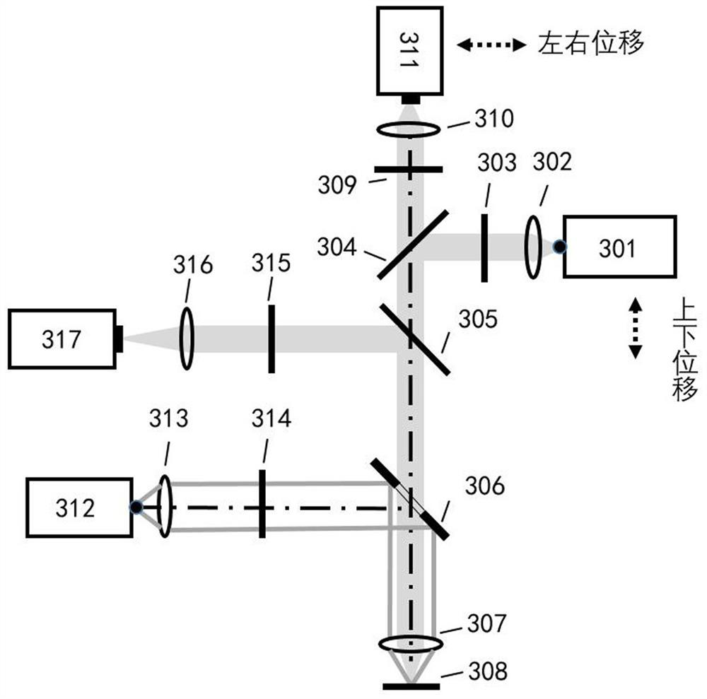
[0031] Another feature different from Embodiment 1 in Embodiment 2 is the addition of a laser focusing module 420, which can monitor the relative position between the detection system and the wafer in real time during the wafer detection process, and drive the detection system to move to ensure that the objective lens is on the sample. It is the focus state, and its working principle is that the beam emitted by the laser focus module 420 is incident on the dichroic mirror 407, and the dichroic mirror 407 is designed to reflect the beam of this wavelength. The beam passes through the normaski prism 408 and is converged on the wafer 410 by the objective lens 409. The focused beam reflected by the wafer returns to the original path and is received by the focusing module 420 after passing through the objective lens 409, the normaski prism 408, and the dichroic mirror 407. At this time, it can be judged whether the objective lens is in focus according to the characteristics of the r...


PUM


Abstract

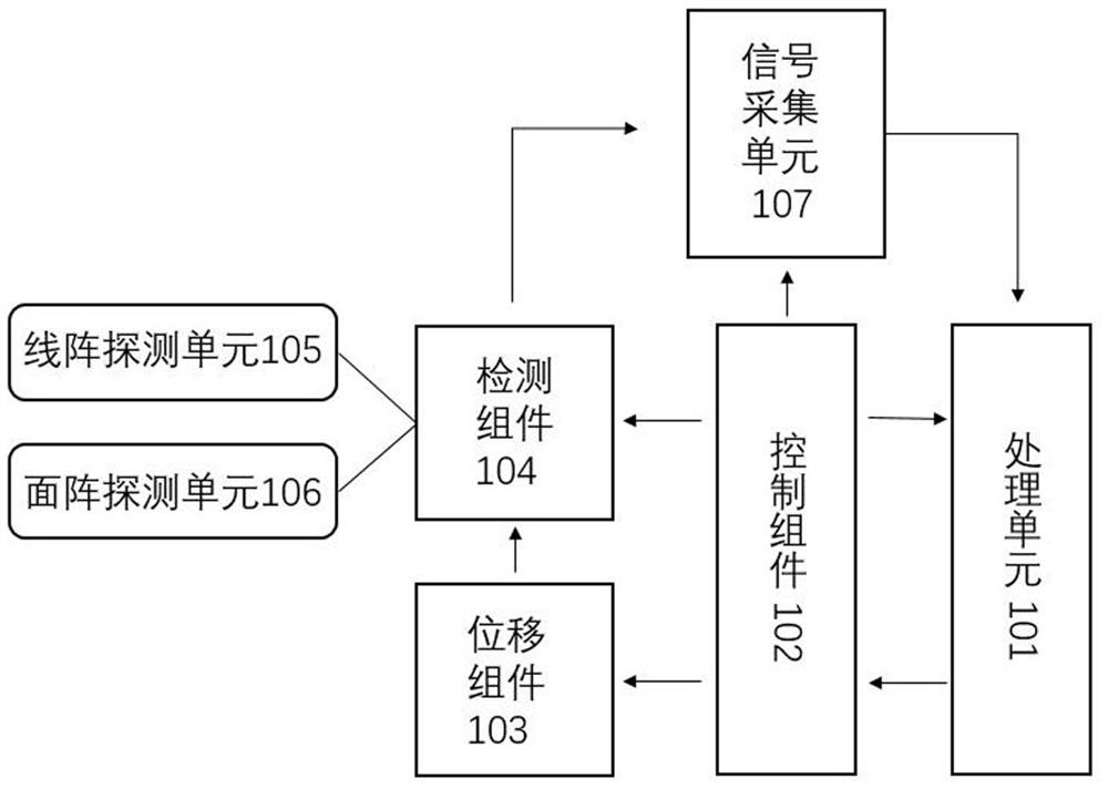
The invention relates to a wafer defect detection system and method. The system comprises a processing unit, a control assembly, a displacement assembly, a detection assembly, and a signal acquisitionunit, the displacement assembly and the detection assembly are cooperatively arranged, and the displacement assembly controls the detection signal acquisition and movement of the detection assembly through displacement. The control assembly controls movement of the displacement assembly through an instruction and indirectly controls detection signal acquisition of the detection assembly, a signalacquired by the detection assembly and instruction information of the control assembly are transmitted to the signal acquisition unit, and the signal acquisition unit transmits the acquired signal tothe processing unit for processing to obtain defect information; the sensitivity requirement of an area array detector is reduced, and the detector cost can be effectively reduced; compared with a traditional scanning mode, the detection speed of the whole system can be greatly increased; and as the area array detector does not move in the area area exposure process, the problem of dithering andblurring of a traditional scanning mode can be solved, and the defect detection and recognition rate is increased.

Description

technical field [0001] The invention belongs to the field of wafer detection, in particular to a wafer defect detection system and method. Background technique [0002] Wafer defect detection refers to detecting whether there are grooves, particles, scratches and other defects in the wafer and recording the defect position and quantity. Wafer defect detection is widely used and is a key link in semiconductor processing. Manual detection is the product surface defect detection However, with the development and progress of society, the traditional detection methods can no longer meet the requirements of detection speed and detection accuracy. With the development of industrial automation, defect detection equipment based on machine vision technology can be used, and defect detection equipment detection High consistency and high accuracy can greatly reduce the cost of employment, which is the trend of wafer defect detection in the future; [0003] Conventionally, there is a ro...

Claims


Application Information

Patent Timeline
Patent Type & Authority Applications(China)
IPC IPC(8): G01N21/95
CPCG01N21/9501
Inventor 杨青王智庞陈雷徐良殷源王立强刘旭
Owner ZHEJIANG LAB
Learn More