Semiconductor device, manufacturing method thereof and chip bonding structure

A manufacturing method and semiconductor technology, applied in semiconductor devices, semiconductor/solid-state device manufacturing, semiconductor/solid-state device components, etc., can solve problems such as reducing the process size and affecting the flatness of the wafer surface

Pending Publication Date: 2021-03-16
WUHAN XINXIN SEMICON MFG CO LTD
View PDF4 Cites 4 Cited by
  • Summary
  • Abstract
  • Description
  • Claims
  • Application Information

AI Technical Summary

Problems solved by technology

However, the ever-decreasing process geometries pose great challenges for CMP
In some special design patterns, such as the process containing through-silicon vias, metal copper is usually filled in the through-silicon vias, and the metal density on the top surface of the wafer where the through-silicon

Method used


Image

  • Semiconductor device, manufacturing method thereof and chip bonding structure
  • Semiconductor device, manufacturing method thereof and chip bonding structure
  • Semiconductor device, manufacturing method thereof and chip bonding structure

Examples


Embodiment Construction

[0057] Embodiments of the present invention provide a semiconductor device, a manufacturing method thereof, and a chip bonding structure. The present invention will be described in further detail below in conjunction with the accompanying drawings and specific embodiments. The advantages and features of the present invention will become clearer from the following description. It should be noted that the drawings are all in a very simplified form and use imprecise scales, and are only used to facilitate and clearly assist the purpose of illustrating the embodiments of the present invention.

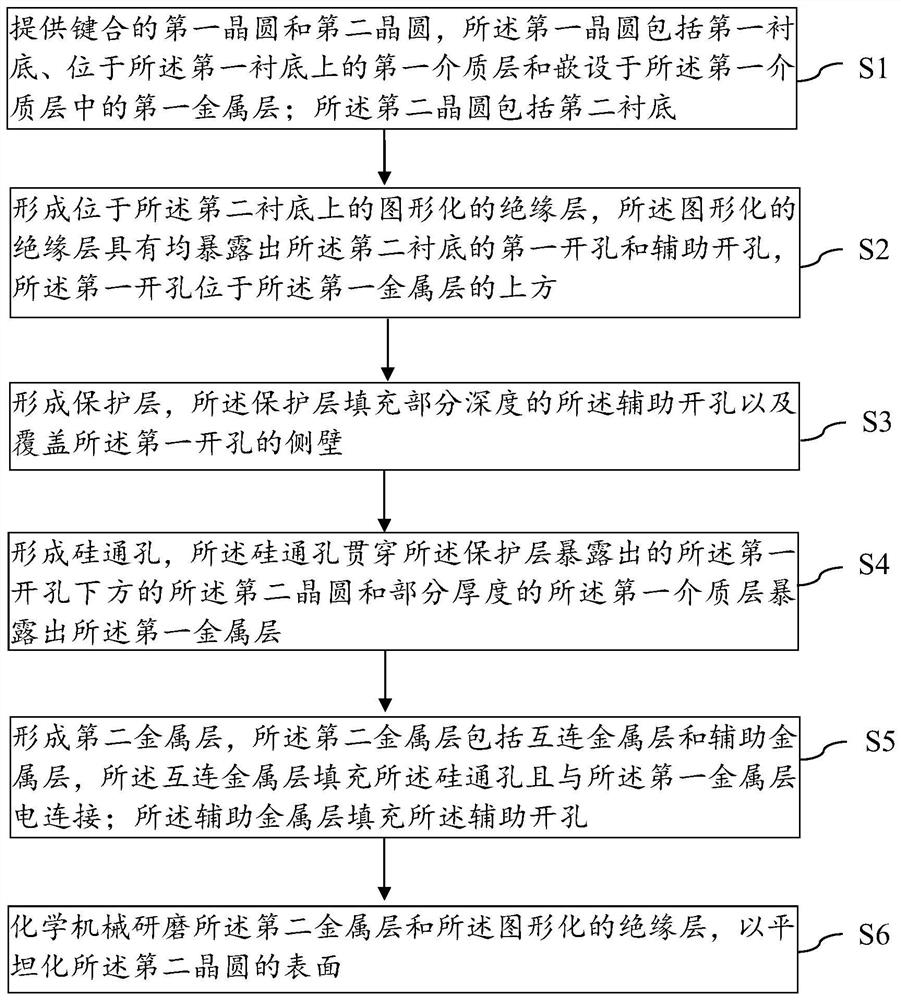
[0058] An embodiment of the present invention provides a method for manufacturing a semiconductor device, such as figure 1 shown, including:

[0059] providing a bonded first wafer and a second wafer, the first wafer comprising a first substrate, a first dielectric layer on the first substrate and embedded in the first dielectric layer the first metal layer; the second wafer includes a ...


PUM


Abstract

The invention provides a semiconductor device and a manufacturing method thereof, and a chip bonding structure. The manufacturing method comprises the steps of providing a first wafer and a second wafer which are bonded; forming a patterned insulating layer on the second substrate, wherein the patterned insulating layer is provided with a first opening and an auxiliary opening which are exposed out of the second substrate; forming a protective layer, wherein the protective layer fills partial depth of the auxiliary hole and covers the side wall of the first hole; forming a silicon through hole; forming a second metal layer, wherein the second metal layer comprises an interconnection metal layer and an auxiliary metal layer, the interconnection metal layer fills the silicon through hole andis electrically connected with the first metal layer, and the auxiliary metal layer fills the auxiliary opening. According to the method, the forming process of the auxiliary metal layer is compatible with the TSV process, no extra process needs to be added, the auxiliary metal layer is formed under the condition that the cost is not increased, the pattern density (metal distribution density) ofthe surface of the second wafer tends to be uniform, the chemical mechanical polishing uniformity is improved, and therefore the flatness of the surface of the wafer obtained after CMP is improved.

Description

technical field [0001] The invention belongs to the technical field of integrated circuit manufacturing, and in particular relates to a semiconductor device, a manufacturing method thereof, and a chip bonding structure. Background technique [0002] In semiconductor technology, chemical mechanical polishing (CMP) is an important process method used to planarize the wafer surface in the VLSI stage. A wafer with high flatness will greatly reduce the difficulty of subsequent processes and improve the accuracy and stability of subsequent processes. CMP usually forms a smooth and flat surface on the surface of the polished medium by means of the chemical corrosion of the polishing liquid and the grinding of ultrafine particles. However, the ever-decreasing process size makes CMP face great challenges. In some special design patterns, such as the process containing through-silicon vias, metal copper is usually filled in the through-silicon vias, and the metal density on the top ...

Claims


Application Information

Patent Timeline
IPC IPC(8): H01L21/18H01L23/48H01L21/306
CPCH01L21/185H01L23/481H01L21/30625
Inventor 曾甜占迪刘天建
Owner WUHAN XINXIN SEMICON MFG CO LTD
Why Eureka
Try Eureka