Adsorption array and cryogenic pump with adsorption array

A cryogenic plate and adsorption material technology, applied in pumps, liquid displacement machines, machines/engines, etc., can solve the problems of not being able to directly and quickly reach the adsorption material and affect the pumping speed, so as to improve the pumping speed, improve performance, The effect of increasing the adhesion area

Inactive Publication Date: 2021-03-19
VACREE TECH
View PDF6 Cites 3 Cited by
  • Summary
  • Abstract
  • Description
  • Claims
  • Application Information

AI Technical Summary

Problems solved by technology

[0007] The technical problem to be solved by the present invention is: in the prior art, H 2 Can not directly and quickly reach the adsorption material and be captured, affecting the cryopump for H 2 pumping speed

Method used


Image

  • Adsorption array and cryogenic pump with adsorption array
  • Adsorption array and cryogenic pump with adsorption array
  • Adsorption array and cryogenic pump with adsorption array

Examples


Embodiment 1

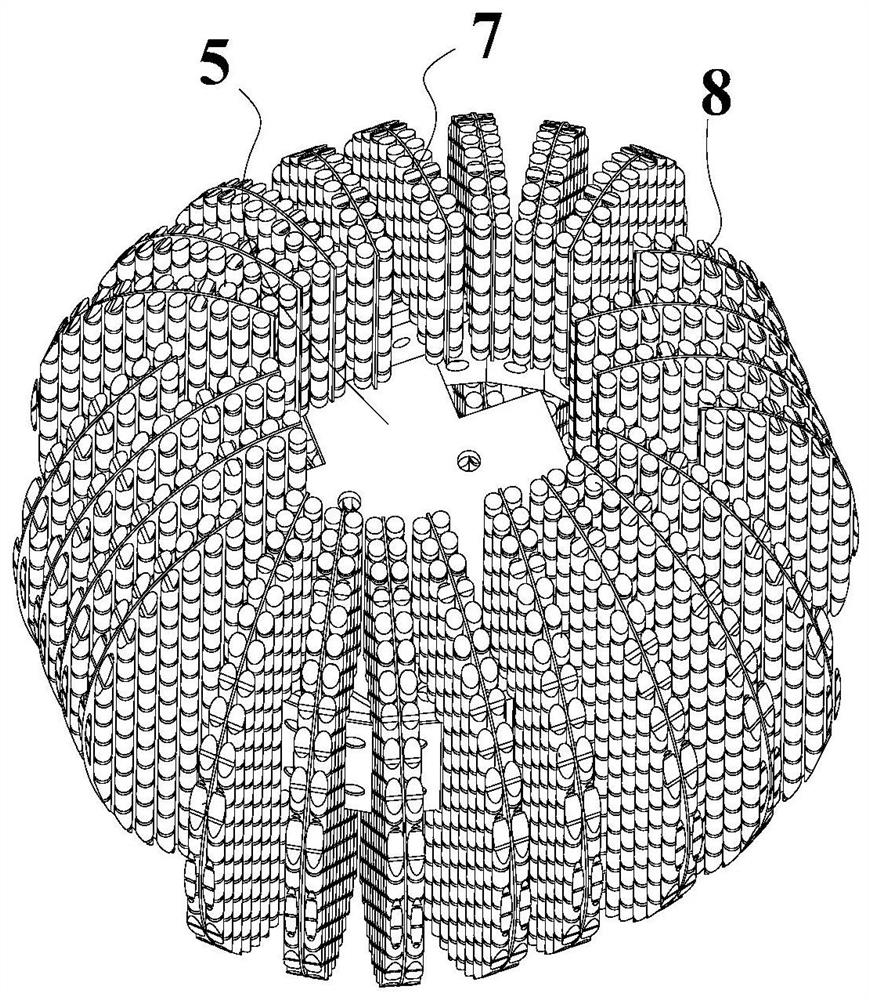
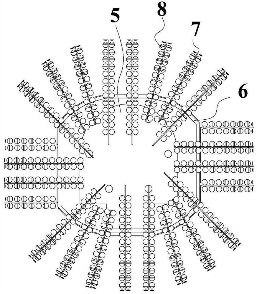
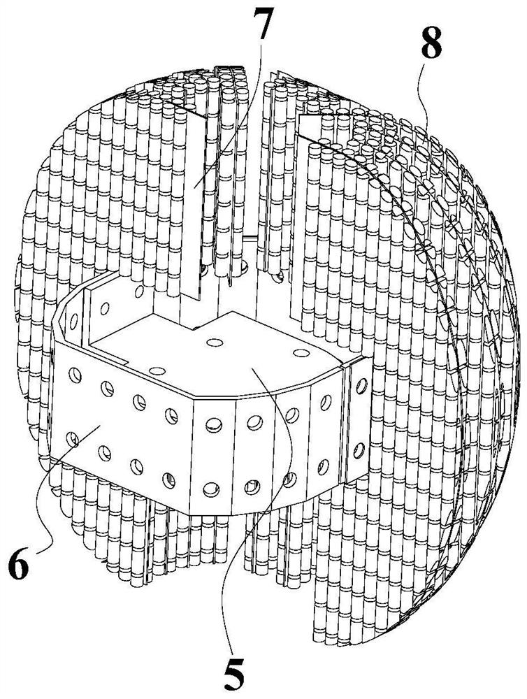
[0050] like figure 1 , 2 As shown, an adsorption array includes a connection plate 5 , a heat transfer plate 6 , a cryogenic plate 7 , and an adsorption material 8 .

[0051] like Figure 5 As shown, the heat transfer plate 6 is annular, and the inside of the heat transfer plate 6 is provided with a connection plate 5, and the surface of the heat transfer plate 6 is perpendicular to the connection plate 5; Figure 1-3 As shown, several low-temperature panels 7 are arranged on the outer surface of the heat transfer plate 6, all the low-temperature panels 7 are perpendicular to the connecting plate 5, and the low-temperature panels 7 are perpendicular to the surface of the heat transfer plate 6 where they are located. The inner side of the cryopanel 7 faces the inside of the heat transfer plate 6, and the outer contour of the cryopanel 7 is arc-shaped; further, the outer contours of all the cryopanels 7 are located on the same virtual spherical surface, and the cryopanel 7 is ...

Embodiment 2

[0064] like Figure 12 , 13As shown, a cryopump includes the above-mentioned adsorption array, and also includes a refrigerator 1 , a casing 2 , a radiation cold shield 3 , and a baffle 4 .

[0065] like Figure 12 , 13 As shown, the primary cooling stage 11 and the secondary cooling stage 12 of the refrigerator 1 are located in the casing 2 . In this embodiment, the low-temperature cold source adopts a G-M refrigerator, which has the characteristics of simple structure, low frequency, and few low-temperature moving parts. The refrigerator adopts bipolar refrigeration, which has a primary cooling stage 11 with a first cooling temperature and a secondary cooling stage 12 with a second cooling temperature. The primary cooling stage 11 is cooled to 65-100K, and the secondary cooling stage 12 is cooled to 10-15K.

[0066] The shell 2 is a cylindrical first shell, the bottom of the first shell is a spherically raised bottom, a horizontal cylinder is arranged on the side of the...


PUM


Abstract

The invention discloses an adsorption array and a cryogenic pump with the adsorption array. The adsorption array comprises a heat transfer plate and a connecting plate, wherein a plurality of cryogenic plates are arranged on the heat transfer plate, the outer contours of the cryogenic plates are in a circular arc shape, and the outer contours of all the cryogenic plates are located on the same virtual spherical surface; and an adsorption material is arranged on each cryogenic plate. The cryogenic pump comprises the adsorption array, a refrigerating machine and a shell, wherein a radiation shield is arranged in the shell; the adsorption array is installed at the end part of a second-stage cooling stage through the connecting plate; the connecting plate is perpendicular to the axis of the second-stage cooling stage; the second-stage cooling stage and the adsorption array are both located in the radiation shield; a baffle is arranged at an opening of the radiation shield; a pump opening flange is arranged at the opening of the shell; and the opening direction of the radiation shield is the same as that of the shell, the axis of the radiation shield coincides with the axis of the shell, and the axes of a first-stage cooling stage and the second-stage cooling stage are perpendicular to the axis of the radiation shield. The cryogenic pump has the advantages that H2 can directly and quickly reach the adsorption material and is captured, and the pumping speed of the cryogenic pump on the H2 is increased.

Description

technical field [0001] The invention relates to the field of cryogenic vacuum technology, in particular to an adsorption array and a cryogenic pump with the adsorption array. Background technique [0002] Cryopumps are vacuum pumps that use condensed gas on low-temperature surfaces to obtain ultra-high vacuum mainly through low-temperature condensation and low-temperature adsorption. Low temperature condensation mainly uses cryopanels to condense the first and second types of gases (such as CO 2 , N 2 , Ar, etc.), with N 2 For example, if the cryopanel temperature is less than or equal to 20K, the pressure will be less than 10 -8 Pa. However, it is not enough to obtain ultra-high vacuum only by low-temperature condensation. The third type of gas H 2 The equilibrium vapor pressure of , He, and Ne at 20K is too high to be condensed on the cryopanel by low temperature. Low-temperature adsorption mainly uses low-temperature adsorption materials to capture the third type of...

Claims


Application Information

Patent Timeline
Patent Type & Authority Applications(China)
IPC IPC(8): F04B37/08F04B37/04
CPCF04B37/08F04B37/04
Inventor 杨杨邓家良曾环武义锋
Owner VACREE TECH
Why Eureka
Try Eureka