Solar heat collection system

A technology of solar energy and photovoltaic systems, applied in the field of F24S solar energy and solar energy, can solve the problems of long total investment recovery period, high maintenance cost, wind and rain of solar heat collector tubes, etc., reduce the proportion of initial investment and power generation costs, and improve the market The effect of improving competitiveness and improving overall efficiency

Active Publication Date: 2021-03-19
浙江态能动力技术有限公司 +1
View PDF0 Cites 0 Cited by
  • Summary
  • Abstract
  • Description
  • Claims
  • Application Information

AI Technical Summary

Problems solved by technology

At present, the development and utilization of solar energy in my country is less than 100 million tons of standard coal, and there is a lot of room for development and utilization. Among them, solar heat storage, heating, heating and cooling systems across seasons are clean and environmentally friendly, and more and more attention has been paid to them. However, due to low energy density, Due to the influence of day and night changes and cloudy, rainy and snowy weather, large-scale development and utilization of solar energy for heating and cooling is facing challenges
[0005] At present, a lot of research and practice have been carried out on solar thermal storage systems at home and abroad, and some progress has been made, but there are still many shortcomings. For example, the existing solar thermal storage project units have high heat collection investment and the total investment recovery period is relatively long. ; The maintenance cost is high, and the outdoor solar collector tube is exposed to wind and rain and is easily damaged, requiring irregular maintenance and replacement
At present, the solar heat storage system only stores all the solar energy in the heat accumulator, without distinguishing the difference between the temperature of the heat source, resulting in an unnecessary and sufficient heat storage process, resulting in the heat exchanger not having enough heat for heat exchange, thus resulting in solar energy storage. Heat energy is difficult to classify and utilize

Method used


Image

  • Solar heat collection system
  • Solar heat collection system
  • Solar heat collection system

Examples


Embodiment Construction

[0030] In order to illustrate the technical features of the solution more clearly, the solution will be described below through specific implementation modes.

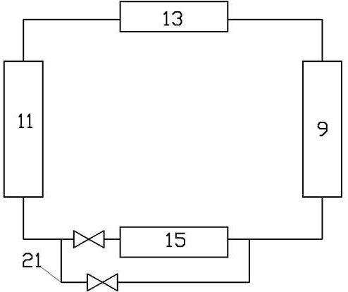
[0031] Such as figure 1 A solar energy system shown, the system includes a mirror field system 11, a high temperature molten salt tank 15, a low temperature molten salt tank 13 and a heat exchanger 9, and the mirror field system 11 includes a liquid outlet pipeline and a liquid return pipeline A heat exchanger 9 is connected between the liquid outlet pipeline and the liquid return pipeline, the high-temperature molten salt tank 15 is arranged on the liquid outlet pipeline, and the low-temperature molten salt tank 13 is arranged on the liquid return pipeline. A bypass line 21 is set on the pipeline of the high temperature molten salt tank 15, a bypass valve is set on the bypass line, and a high temperature valve is set on the inlet line of the high temperature molten salt tank 15.

[0032] A temperature sensor is arran...


PUM


Abstract

A solar system comprises a mirror field system, a high-temperature molten salt tank, a low-temperature molten salt tank and a heat exchanger. The mirror field system comprises a liquid outlet pipelineand a liquid return pipeline, the heat exchanger is connected between the liquid outlet pipeline and the liquid return pipeline, the high-temperature molten salt tank is arranged on the liquid outletpipeline, and the low-temperature molten salt tank is arranged on the liquid return pipeline; a bypass pipeline is arranged on a pipeline of the high-temperature molten salt tank, a bypass valve is arranged on the bypass pipeline, and a high-temperature valve is arranged on an inlet pipeline of the high-temperature molten salt tank; and a temperature sensor is arranged on the liquid outlet pipeline and used for detecting the temperature of a heat source output by a heat collector, and a controller automatically controls opening and closing of the bypass valve and the high-temperature valve according to the detected temperature of the heat source. The invention provides the novel solar heat storage system which can select either to store heat or directly enter the heat exchanger for heat exchange by detecting the temperature of the heat source; if the temperature is too low, the heat exchange requirement of the heat exchanger must be met firstly, and therefore heat storage is not conducted; and if the temperature is too high, heat storage can be conducted, and entering into the heat exchanger for heat exchange is carried out after heat storage. The solar heat storage heat energy isutilized according to the temperature, and the utilization efficiency of solar energy is improved.

Description

technical field [0001] The invention belongs to the field of solar energy, and specifically relates to a solar heat storage system and a heating system, and relates to the field of F24S solar energy. Background technique [0002] In recent years, China's dependence on foreign energy has continued to increase, and the energy security situation is not optimistic; the total energy consumption has grown rapidly. In 2016, China's total energy consumption reached 4.36 billion tons, accounting for 23% of the world's total energy consumption, ranking first in the world. First, building heating loads and air-conditioning cooling loads continue to rise, and per capita electricity consumption has increased significantly. However, compared with international developed countries, there is still a big gap between China's per capita energy consumption and per capita electricity consumption; the total amount of greenhouse gas emissions is large. , the pressure to cope with climate change is...

Claims


Application Information

Patent Timeline
IPC IPC(8): F24S20/20F24S23/77F24S50/40F24S60/30H02J3/38H02J7/35H02K7/18H02S10/30
CPCF24S20/20F24S23/77F24S50/40F24S60/30H02J7/35H02S10/30H02J3/381H02K7/1846H02J2300/24Y02E10/40Y02E10/56
Inventor 不公告发明人
Owner 浙江态能动力技术有限公司
Why Eureka
Try Eureka