A kind of rolling saggar rolling progressive mechanism and rolling progressive method

A technology for a rotary drive mechanism and a saggar is applied in the field of high-temperature sintering furnaces, which can solve the problems of the uncontrolled rotation speed of the sagger, reduce the reliability of the whole machine, reduce the reliability and life of the whole machine, etc. Gear occlusion failure, rich effects applicable to scenes

Active Publication Date: 2022-07-08
JIANGSU JITRI MOLECULAR ENG INST CO LTD
View PDF6 Cites 0 Cited by
  • Summary
  • Abstract
  • Description
  • Claims
  • Application Information

AI Technical Summary

Problems solved by technology

[0004] In practical application, it is found that this type of tunnel kiln has the following problems: First, the length of the push plate propulsion mechanism is usually very long, which is not suitable for placing in the laboratory for small powder sintering tests, which limits its application scenarios. Moreover, the hydraulic drive mechanism usually used to push the push plate forward often has problems such as high mechanical failure rate and easy oil leakage.
Secondly, the drive mechanism that drives the sagger to rotate by means of gears, racks or chains in this patent document is prone to problems such as occlusal failure and adhesion on the surface of the device under the action of high temperature and dust in the tunnel kiln. The rotation speed of the sagger is out of control, and on the other hand, the reliability and life of the whole machine are also reduced.
In addition, some powder sintering processes require different turning rates at different stages, which requires that the rotation speed of each saggar be flexible and controllable at different positions in the kiln. In the kiln given in the aforementioned patent documents Among them, it can only be realized by increasing the number of racks / chains, which further reduces the reliability of the whole machine and also increases the cost

Method used


Image

  • A kind of rolling saggar rolling progressive mechanism and rolling progressive method
  • A kind of rolling saggar rolling progressive mechanism and rolling progressive method
  • A kind of rolling saggar rolling progressive mechanism and rolling progressive method

Examples


Embodiment 1

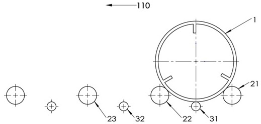
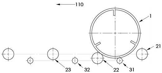
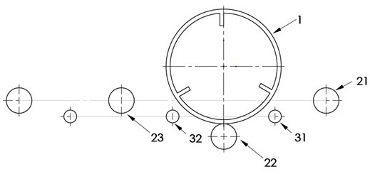
[0037] The present embodiment provides a rolling sagger tumbling and advancing mechanism. like figure 1 Shown is a schematic cross-sectional view of the first rolling saggar tumbling and advancing mechanism of the present invention in the first state, which includes a saggar 1, three equidistantly spaced elevating wheels and two equidistantly spaced supporters wheel. The lifting wheel and the supporting wheel are cylindrical bodies made of ceramic materials. The outer contour of the saggar 1 is a cylinder. The axes of the lifting wheel, the supporting wheel and the saggar 1 are parallel to each other in three-dimensional space.

[0038] The lift wheels include a first lift wheel 21 , a second lift wheel 22 and a third lift wheel 23 . The supporting roller includes a first supporting roller 31 and a second supporting roller 32 . The above-mentioned lifting wheels and supporting wheels are arranged at intervals, that is, there is a lifting wheel between every two supporting...

Embodiment 2

[0048] Image 6 Shown is a schematic cross-sectional view of another rolling saggar tumbling and advancing mechanism provided by an embodiment of the present invention, including: a saggar 1 , a first lifting wheel 21 , a second lifting wheel 22 , and a third lifting wheel 23 . The lifting wheel is a cylinder made of ceramic material. The outer contour of the saggar 1 is a cylinder. The axes of the lifting wheel and the saggar 1 are parallel to each other in three-dimensional space. The distance between the axes of two adjacent lifting wheels is smaller than the radius of the cross section of the outer contour of the saggar 1 . The outer contour of the saggar 1 is tangent to the two adjacent lifting wheels for support. Each lifting wheel is connected with an independent lifting mechanism (not shown in the figure) so that each lifting wheel can be lifted and lowered independently in the vertical direction. And each lift wheel is also connected with an independent rotary dri...

Embodiment 3

[0056] Except for the following description, the tumbling and advancing method of the tumbling and advancing mechanism of the rolling sagger provided in this embodiment is the same as that of the second embodiment. In the third state, while the third lifting wheel 23 descends, the second lifting wheel 22 rises. Under the combined action of gravity and the rising thrust of the second lifting wheel 22, the saggar 1 rolls in the forward direction 110, during which the saggar 1 rolls over. , the second lift wheel 22 and the third lift wheel 23 remain tangent. When the heights of the third lifting wheel 23 and the second lifting wheel 22 are the same, the Figure 9 the fourth state shown. The third lifting wheel 23 does not continue to descend, but turns to rise in synchronization with the second lifting wheel 22, and finally reaches the fifth state.


PUM


Abstract

A rolling saggar rolling progressive mechanism and rolling progressive method belong to the technical field of high temperature sintering kilns. A rolling sagg rolling progressive mechanism, which comprises a plurality of lifting wheels which are cylinders, the axes of the lifting wheels and the axis of the sagger are parallel to each other in three-dimensional space, and the distance between the axes of two adjacent lifting wheels is smaller than that outside the saggar. The diameter of the profile cross-section, each lifting wheel is connected to an independent lifting mechanism so that each lifting wheel can be lifted and lowered independently in the vertical direction. The tumbling advancement method of the tumbling advancement mechanism of the rolling saggar utilizes the lifting and lowering coordination of the lifting wheels to realize the advancement of the saggar in the advancing direction. The above-mentioned rolling saggar tumbling advancement mechanism and tumbling advancement method can shorten the overall length of the kiln, the rotation speed of the sagger can be adjusted, the overall mechanical structure is reliable, and the sintering requirements of related materials can be met.

Description

technical field [0001] The invention belongs to the technical field of high-temperature sintering kilns, and in particular relates to a rolling sagger tumbling progressive mechanism and a tumbling progressive method. Background technique [0002] High temperature sintering furnace is an important heating equipment commonly used in the industry, which is widely used in powder sintering or green body sintering of active metals, refractory metals and their alloys, ceramic materials, and dissimilar materials. Traditional high-temperature sintering furnaces can be mainly divided into push-plate kilns and rotary kilns according to their structure. The main body of the push-plate kiln is a tunnel-type high-temperature kiln body, and the saggars containing the materials to be sintered are lined up in sequence to push the kiln body from the kiln head. After a period of high-temperature sintering in the kiln, the saggars are constantly being sintered. The horizontal sequence moves, b...

Claims


Application Information

Patent Timeline
Patent Type & Authority Patents(China)
IPC IPC(8): F27B9/26F27B9/30F27B9/38F27B9/40
CPCF27B9/26F27B9/30F27B9/38F27B9/40
Inventor 霍继延陈建中
Owner JIANGSU JITRI MOLECULAR ENG INST CO LTD
Why Eureka
Try Eureka