
Design and construction method of T-shaped rectangular steel tube-corrugated steel plate composite wall

A technology of rectangular steel pipes and combined walls, which is applied in the direction of walls, building components, building types, etc., can solve the problems of complex structure of T-shaped shear wall-steel beam joints, difficult on-site connection of vertical components, and high overall cost, so as to improve Common work performance, reduction of fire protection coating area, and improvement of construction efficiency

Inactive Publication Date: 2021-03-23
TONGJI UNIV
View PDF7 Cites 1 Cited by
  • Summary
  • Abstract
  • Description
  • Claims
  • Application Information

AI Technical Summary

Problems solved by technology

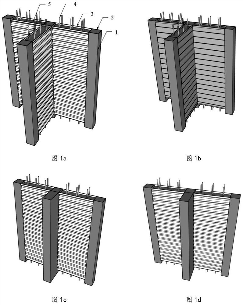
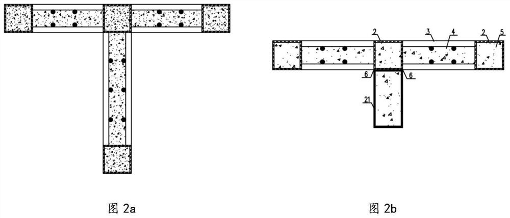
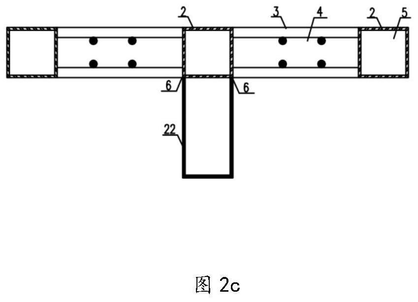
[0003] The purpose of this application is to provide a design and construction method for a T-shaped rectangular steel tube-corrugated steel plate composite wall based on the overall design concept of load-bearing and anti-side separation. The rectangular steel tube concrete column formed by comprehensive utilization has high bearing performance and is easy to manufacture and install. And corrugated steel plate out-of-plane rigidity, good local buckling bearing capacity and other advantages, through reasonable combination, solve the complex structure of T-shaped shear wall-steel beam joint structure of the existing prefabricated steel-concrete composite structure, difficult field connection of vertical components, and Problems such as large amount of steel, difficult fabrication and installation, and high overall cost

Method used


Image

  • Design and construction method of T-shaped rectangular steel tube-corrugated steel plate composite wall
  • Design and construction method of T-shaped rectangular steel tube-corrugated steel plate composite wall
  • Design and construction method of T-shaped rectangular steel tube-corrugated steel plate composite wall

Examples


Embodiment Construction

[0040] The technical solutions provided by the present application will be further described below in conjunction with specific embodiments and accompanying drawings. The advantages and features of the present application will become clearer in conjunction with the following description.

[0041] A method for designing and implementing a T-shaped rectangular steel pipe-corrugated steel plate composite wall (1), characterized in that:

[0042] Process 1: Factory prefabrication

[0043] In terms of composition, it includes a rectangular steel pipe column (2), a corrugated steel plate (3), and a steel mesh sheet (4), wherein: the rectangular steel pipe column (2) can be formed by cold bending or welded by steel plates; The end rectangular steel pipes (2) are connected by welds, and are placed horizontally along the corrugation, and the outermost sides of the crests are flush with the outer sides of the rectangular steel pipes; the steel mesh (4) is formed by spot welding or bind...


PUM


Abstract

The invention relates to the field of building structure engineering, in particular to a design and construction method of a T-shaped rectangular steel tube-corrugated steel plate composite wall. Themethod comprises the following processes that process 1: factory fabrication is conducted, specifically, rectangular steel tubular columns, corrugated steel plates and reinforcing meshes are manufactured and assembled in a factory to form a composite wall framework; process 2: on-site installation and pouring are conducted, then integral transporting is conducted to a construction site, and pouring concrete is conducted: specifically, filled concrete (5) is poured into a cavity formed by the rectangular steel tubular columns (2) and the corrugated steel plates (3) with the reinforcing meshes (4) on the two sides to form the T-shaped rectangular steel tube-corrugated steel plate composite wall (1); and process 3: fire-resistant treatment is conducted. The problem of out-of-plane instabilityof a formwork during concrete pouring and the problem that the steel plates are prone to local instability when a component bears a horizontal load are solved; the formed T-shaped composite wall is convenient to construct and install, and an effective use area of a building is expanded; and in addition, the method has the advantages of being simple in structure, reasonable in design, excellent inmechanical property, low in manufacturing cost, suitable for assembly type construction and the like.

Description

technical field [0001] This application relates to the field of architectural structural engineering. Background technique [0002] The prefabricated steel-concrete composite structure residence has the advantages of high degree of industrialization, good quality of parts, short construction period, good seismic performance, and high comprehensive technical and economic indicators. It is one of the prefabricated building systems supported by the state. Existing multi-story prefabricated steel-concrete composite structures can generally be divided into steel-concrete composite column frame-support (shear wall) structures, steel-concrete composite shear walls (steel tube beam concrete shear walls or steel plate shear walls Walls, etc.) structure two types of structural systems. In order to meet the functional requirements of residential buildings and user habits, flexible layout of the building plane is required, resulting in the staggered layout of the axes of each room. Whe...

Claims


Application Information

Patent Timeline
IPC IPC(8): E04B2/56E04B2/64E04H9/02E04B1/98
CPCE04B1/98E04B2/56E04B2/64E04H9/021E04H9/025
Inventor 罗金辉李国强刘青陈琛
Owner TONGJI UNIV
Learn More