
NFC antenna assembly and electronic device

An antenna assembly and antenna radiator technology, which is applied to antenna supports/installation devices, loop antennas with ferromagnetic material cores, radiating element structures, etc. The effect of improving performance and reducing the number of laps

Active Publication Date: 2021-03-23
GUANGDONG OPPO MOBILE TELECOMM CORP LTD
View PDF15 Cites 0 Cited by
  • Summary
  • Abstract
  • Description
  • Claims
  • Application Information

AI Technical Summary

Problems solved by technology

, however, the multi-turn coil approach leads to an increase in the mass of the NFC antenna

Method used


Image

  • NFC antenna assembly and electronic device
  • NFC antenna assembly and electronic device
  • NFC antenna assembly and electronic device

Examples


Embodiment Construction

[0028] Embodiments of the present application are described in detail below, examples of which are shown in the drawings, wherein the same or similar reference numerals denote the same or similar elements or elements having the same or similar functions throughout. The embodiments described below by referring to the figures are exemplary, and are only for explaining the present application, and should not be construed as limiting the present application.

[0029] The following describes an NFC (Near Field Communication, NFC for short) antenna assembly 10 according to an embodiment of the present application with reference to the accompanying drawings.

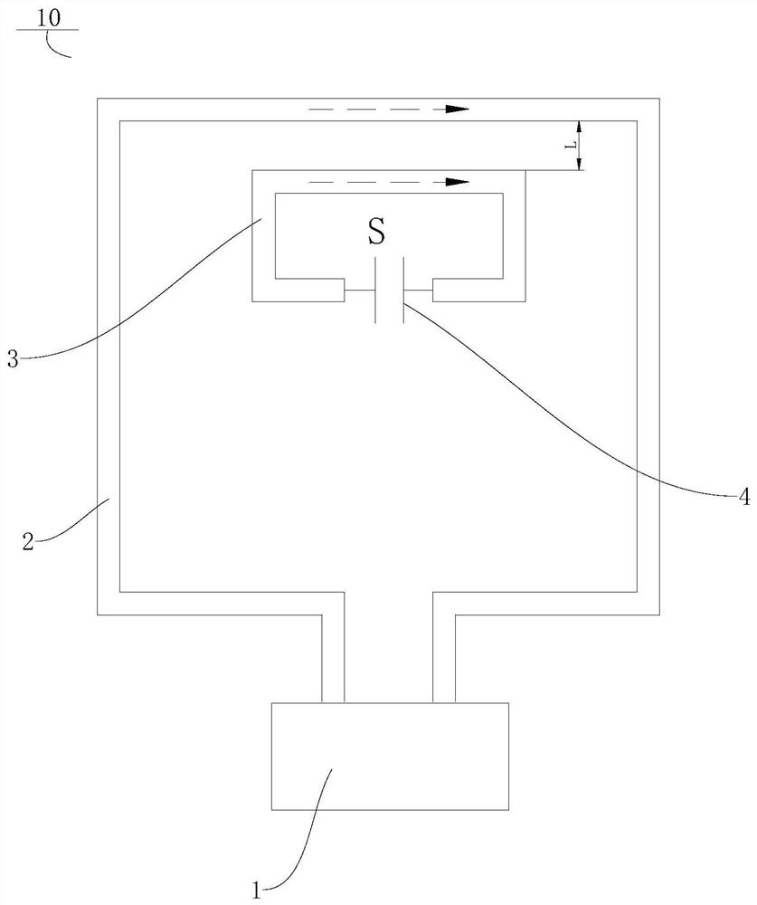
[0030] Such as figure 1 As shown, the NFC antenna assembly 10 according to the embodiment of the present application includes an NFC driver chip 1 , an NFC antenna radiator 2 and a coupling piece.

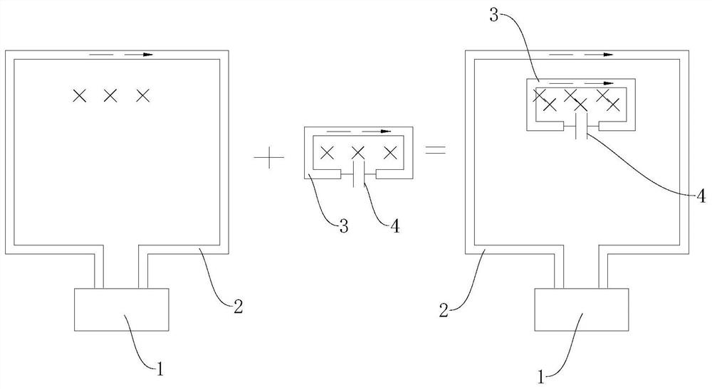
[0031] Specifically, such as figure 1 As shown, the NFC antenna radiator 2 is connected with the NFC driver chip 1, the NFC ante...


PUM


Abstract

The invention discloses an NFC antenna assembly and an electronic device. The NFC antenna assembly comprises an NFC driving chip, NFC antenna radiator which is connected with the NFC driving chip, anda coupling piece which is located in the radiation range of the NFC antenna radiator; the coupling piece and the NFC antenna radiator are spaced; and the coupling piece and the NFC antenna radiator can be coupled with each other, so that the current passing through the NFC antenna radiator and the current passing through the coupling piece are consistent in direction. According to the NFC antennaassembly, the coupling piece spaced from the NFC antenna radiator is added in the radiation range of the NFC antenna radiator, and the coupling piece and the NFC antenna radiator can be coupled witheach other, so that the current passing through the NFC antenna radiator and the current passing through the coupling piece are consistent in direction, the magnetic field intensity can be effectivelyenhanced, and the performance of the NFC antenna assembly is improved. And meanwhile, the number of turns of an NFC antenna radiator coil is reduced, so that the weight of a whole machine is reduced.In addition, the coupling piece can be independently processed, is flexible and convenient in design, and can be placed at different positions as required.

Description

technical field [0001] The present application relates to the technical field of NFC antennas, in particular to an NFC antenna assembly and electronic equipment. Background technique [0002] In related technologies, NFC (Near Field Communication, NFC for short) antennas have been increasingly applied to electronic devices such as mobile phones. In order to improve the radiation intensity of the NFC antenna, in the prior art, the performance is mainly improved by arranging a multi-turn coil. , However, the way of multi-turn coils leads to an increase in the quality of the NFC antenna. Contents of the invention [0003] The present application proposes an NFC antenna assembly. The NFC antenna assembly has a strong magnetic field strength and is conducive to reducing the number of radiator coils of the NFC antenna. [0004] The present application also proposes an electronic device, which includes the above-mentioned NFC antenna assembly. [0005] The NFC antenna assembly...

Claims


Application Information

Patent Timeline
Patent Type & Authority Applications(China)
IPC IPC(8): H01Q1/36H01Q7/06H01Q1/22
CPCH01Q1/36H01Q7/06H01Q1/22
Inventor 李偲
Owner GUANGDONG OPPO MOBILE TELECOMM CORP LTD
Learn More