
Micro-vibration plant protection unmanned aerial vehicle

A plant protection drone and micro-vibration technology, applied to aircraft parts, devices for catching or killing insects, landing gear, etc., can solve the vibration of the pump body, wear of the medicine box, increase the wear of the medicine box and the entire frame, etc. problem, to achieve the effect of ensuring synchronization and reducing vibration

Pending Publication Date: 2021-03-26
河南正大航空工业股份有限公司
View PDF0 Cites 1 Cited by
  • Summary
  • Abstract
  • Description
  • Claims
  • Application Information

AI Technical Summary

Problems solved by technology

[0003] At present, when the plant protection drone sprays pesticides, it is necessary to use a pump to pump out the pesticide. The plunger pump is the most used by several leading plant protection drone brands in China. The plunger pump needs to pass through the internal plunger when it is working. When the liquid medicine is pumped out, the vibration of the pump body will be caused when the plunger is reciprocating and fast, and the vibration will be transmitted to the whole plant protection drone through the fixing frame of the pump body, thus affecting the normal work of the plant protection drone , will increase the wear between the medicine box and the entire frame, and it is easy to wear the medicine box through; and the bottom bracket of the existing plant protection drone is generally U-shaped with an upward opening, and must be able to stop on a flat ground. However, after the rain, the roads in the field are muddy, and there will be wheel marks left after driving. It is difficult to find a flat ground without crops in the field, making it difficult for existing drones to stop

Method used


Image

  • Micro-vibration plant protection unmanned aerial vehicle
  • Micro-vibration plant protection unmanned aerial vehicle
  • Micro-vibration plant protection unmanned aerial vehicle

Examples


Embodiment Construction

[0027] The following will clearly and completely describe the technical solutions in the embodiments of the present invention with reference to the accompanying drawings in the embodiments of the present invention. Obviously, the described embodiments are only some, not all, embodiments of the present invention. Based on the embodiments of the present invention, all other embodiments obtained by persons of ordinary skill in the art without making creative efforts belong to the protection scope of the present invention.

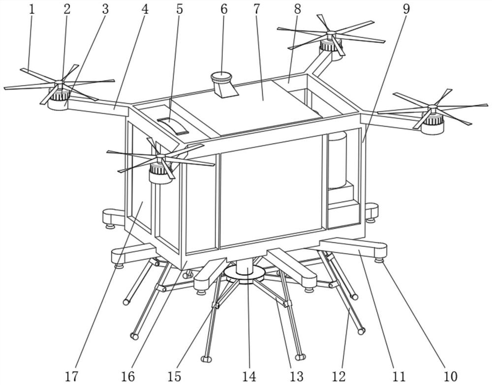
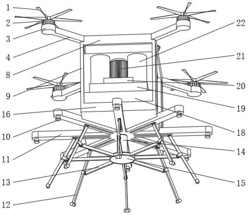
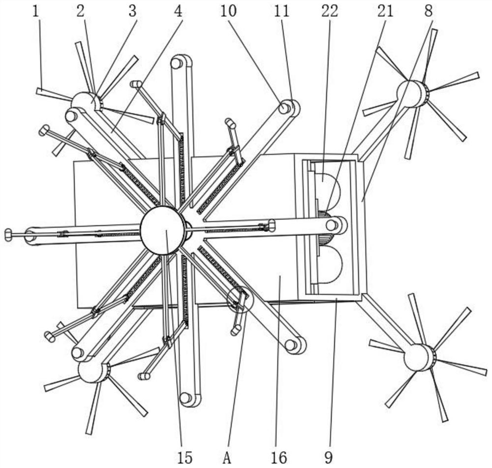
[0028] see Figure 1-6 , a micro-vibration plant protection drone, including a top frame 8 and a bottom plate 16, the middle of the bottom of the bottom plate 16 is fixedly connected with an intermediate column 14, and the bottom of the intermediate column 14 is fixedly connected with an intermediate plate 15, and the intermediate plate 15 moves through a pin shaft Connected with a cross bar 13, the bottom of the base plate 16 is fixedly connected with a spray...


PUM


Abstract

The invention discloses a micro-vibration plant protection unmanned aerial vehicle, and relates to the technical field of plant protection unmanned aerial vehicles. The micro-vibration plant protection unmanned aerial vehicle comprises a top frame and a bottom plate, a middle column is fixedly connected to the middle of the bottom of the bottom plate, a middle disc is fixedly connected to the bottom of the middle column, and a spring box is fixedly connected to one side of the top of the bottom plate. According to the micro-vibration plant protection unmanned aerial vehicle, by arranging a power box, two plunger pumps can be driven to work at the same time through a pesticide pump motor, so that the synchronism of the two plunger pumps is guaranteed, by arranging the spring box, when a vibration reduction plate is affected by the plunger pumps, vibration can be weakened through vibration reduction springs, and the purpose of reducing vibration is achieved; and by arranging a pesticidespraying rod, a landing spring can be arranged in the pesticide spraying rod, a sliding block is jacked tightly through the landing spring, when the unmanned aerial vehicle lands, due to the fact thatthe bottoms of foot rods are not connected, the unmanned aerial vehicle can stop stably on a bumpy road surface, meanwhile, the landing spring is compressed to achieve the effect of reducing vibration, and the purpose of stopping the unmanned aerial vehicle stably is achieved.

Description

technical field [0001] The invention relates to the technical field of plant protection drones, in particular to a micro-vibration plant protection drone. Background technique [0002] At present, with the rapid development of China's agriculture and China's science and technology, drones have been widely used in the agricultural field, such as plant protection drones, agricultural drones are unmanned aerial vehicles used in agriculture, the purpose is to help Improve crop yields and monitor crop growth. Its sensors and digital imaging capabilities can help farmers better understand their fields and help improve crop yields and farm efficiency. The main application of plant protection drones in agriculture is to spray pesticides. Compared with traditional manual spraying of pesticides, it has great advantages. It can save a lot of manpower and greatly improve the efficiency of pesticide spraying. [0003] At present, when the plant protection drone sprays pesticides, it is...

Claims


Application Information

Patent Timeline
IPC IPC(8): A01M7/00B64C25/62B64D1/18
CPCA01M7/0042A01M7/005B64C25/62B64D1/18
Inventor 张雷程军崔磊孙伟路明顺贾啸傲
Owner 河南正大航空工业股份有限公司
Learn More