Welding device with dust and slag removal functions and application method thereof

A welding device and function technology, applied in the field of welding devices with dust removal and slag removal functions, can solve the problems of inability to purify smoke and dust, pollution of the working environment, inability to treat dust and slag, and achieve good practicability, increase efficiency, Easy to clean effect

Inactive Publication Date: 2021-03-26
徐世云
View PDF0 Cites 0 Cited by
  • Summary
  • Abstract
  • Description
  • Claims
  • Application Information

AI Technical Summary

Problems solved by technology

[0003] At present, during the welding process, dust and ash will be generated, and the existing welding devices are often unable to handle the dust and ash well, making it difficult to clean the ash and dust, and the dust cannot be purified, which affects the working environment. Caused pollution, there are certain disadvantages

Method used


Image

  • Welding device with dust and slag removal functions and application method thereof
  • Welding device with dust and slag removal functions and application method thereof
  • Welding device with dust and slag removal functions and application method thereof

Examples


Embodiment 1

[0032] see Figure 1-7 , the present invention provides a technical solution:

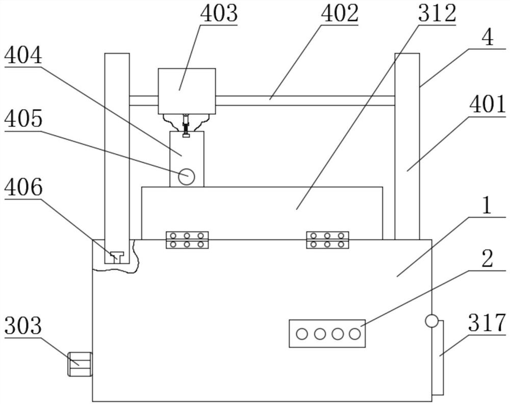
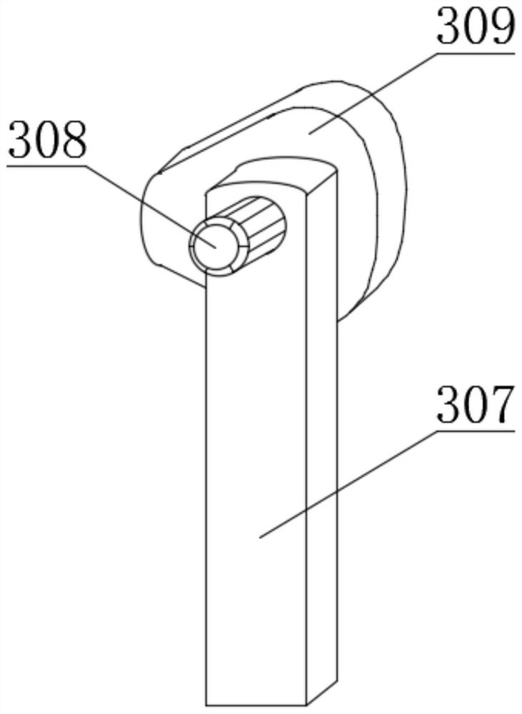
[0033]A welding device with the function of removing dust and slag, comprising a housing 1, a controller 2 at the front end of the housing 1, and a grid plate 5 inside the top end of the housing 1. A slag collecting device 3 is arranged on the inner side of the housing 1, and The slag collecting device 3 comprises a collection tank 301, a support plate 307, a limit ring 306, a connecting plate 313, a first motor 303, a first limit rod 305 and a side plate 312, and the support plate 307 and the limit ring 306 are all fixedly connected to the The inner side of the bottom of the housing 1 and the inner side of the top of the limit ring 306 are slidingly connected to the knock rod 310. The knock rod 310 is arranged on one side of the collection tank 301. The outer side of the knock rod 310 is provided with a spring 311. The two sides of the spring 311 The ends are respectively fixedly connected with t...

Embodiment 2

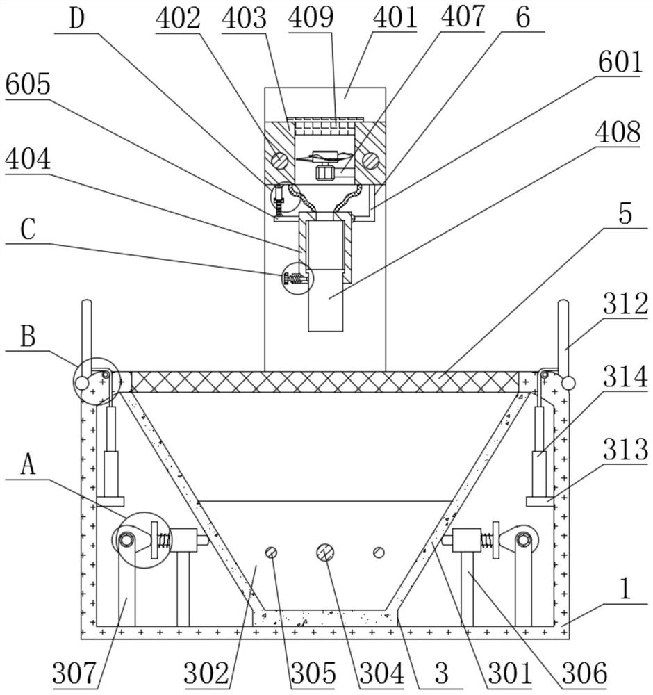
[0037] Embodiment 2: In this embodiment, the same parts as in Embodiment 1 will not be described in detail. What is not needed is that the present invention can also adjust the air suction port of the inner cylinder 408 through the ventilation steering adjustment mechanism 6, which increases the convenience of use When it is necessary to turn around, turn the turntable 603 by hand, the rotation of the turntable 603 will drive the third screw 604 to move upward or downward, and the up and down movement of the third screw 604 will drive the outer cylinder 404 to center on the bottom end of the connecting rod 601 Rotate to realize the adjustment of the position of the air suction port of the inner cylinder 408, which has good practicability.


PUM


Abstract

The invention relates to the technical field of welding devices, in particular to a welding device with dust and slag removal functions and an application method thereof. The welding device comprisesa shell, a controller at the front end of the shell and a grid plate at the inner side of the top end of the shell, wherein a crushed slag collecting device is arranged at the inner side of the shell;the crushed slag collecting device comprises a collecting tank, supporting plates, spacing rings, connecting plates, a first motor, a first limiting rod and side plates; and the supporting plates andthe spacing rings are both fixedly connected to the inner side of the bottom end of the shell. According to the welding device, the crushed slag can be collected and cleaned through the crushed slagcollecting device, the crushed slag generated during welding can fall to the inner side of the collecting tank through the grid plate, the arranged side plates can prevent the crushed slag from splashing to the outer side of the shell, the side plates can be opened when needed and can be folded when not needed, the crushed slag collecting device can shake off the crushed slag at the two sides of the inner side of the collecting tank through vibration, the crushed slag falls into the inner side of the bottom end of the collecting tank in a centralized mode, and the crushed slag is convenient toclean.

Description

technical field [0001] The invention relates to the technical field of welding devices, in particular to a welding device with dust and slag removal functions and a method for using the same. Background technique [0002] Welding, also known as welding and melting, is a manufacturing process and technology for joining metals or other thermoplastic materials such as plastics by means of heating, high temperature or high pressure. Welding can be divided into the following three ways to achieve the purpose of joining, fusion welding, For pressure welding and brazing, a metal material with a lower melting point than the base metal is used as the solder, and the liquid solder is used to wet the base metal, fill the joint gap, and diffuse with the base metal to realize the joint weldment. It is suitable for welding processing of various materials, and also suitable for welding processing of different metals or heterogeneous materials. There are many energy sources for modern weldi...

Claims


Application Information

Patent Timeline
Patent Type & Authority Applications(China)
IPC IPC(8): B23K37/00B08B5/04B01D46/10
CPCB01D46/10B08B5/04B23K37/00
Inventor 徐世云
Owner 徐世云
Why Eureka
Try Eureka