Cutting equipment with adjustable angle fixing structure

A technology for fixing structures and cutting equipment, applied in shearing equipment, metal processing equipment, solid separation, etc., can solve problems such as poor recovery effect, poor use effect, inconvenient cutting on inclined surfaces, etc., to prevent offset, automatic Adapt to the effect of good effect

Inactive Publication Date: 2021-03-26
郑爱兵
View PDF10 Cites 8 Cited by
  • Summary
  • Abstract
  • Description
  • Claims
  • Application Information

AI Technical Summary

Problems solved by technology

[0003] In the process of using the existing cutting machine, it is inconvenient to cut the inclined surface. Generally, when cutting the inclined surface, it is necessary to manually adjust the angle of the cutting blade. When different components are cut, the waste cannot be sorted and collected, and the recycling effect is poor

Method used


Image

  • Cutting equipment with adjustable angle fixing structure
  • Cutting equipment with adjustable angle fixing structure
  • Cutting equipment with adjustable angle fixing structure

Examples


Embodiment 1

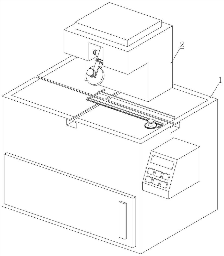
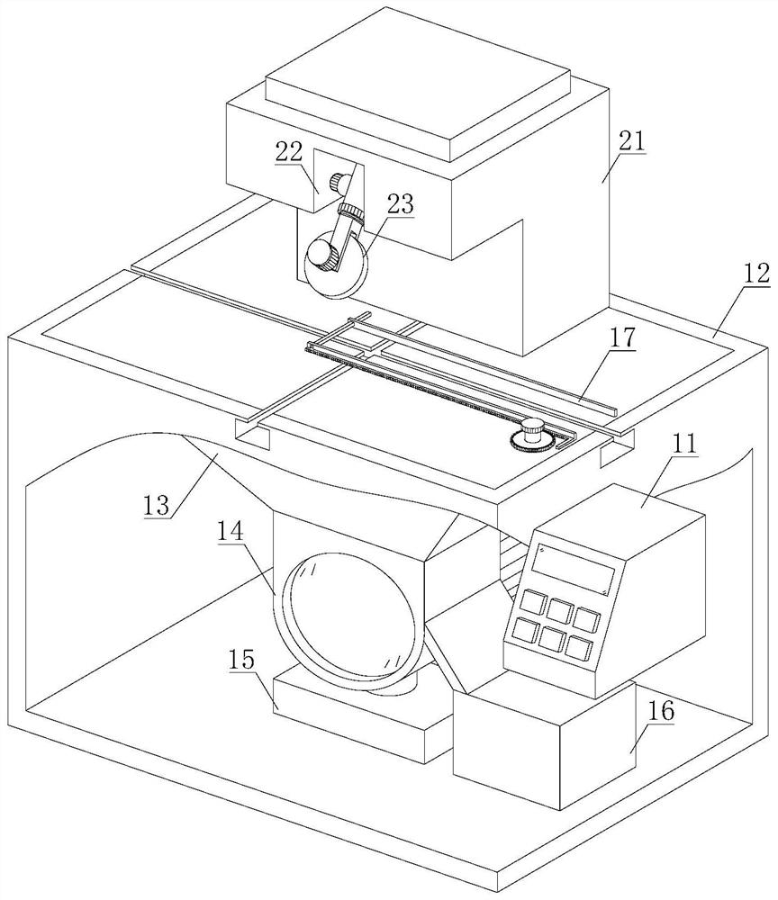
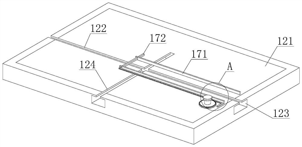
[0030] refer to figure 1 and figure 2, a cutting device with an adjustable angle fixing structure, including a workbench 1 and a cutting assembly 2, the cutting assembly 2 is arranged on the upper end of the workbench 1, and the workbench 1 includes a control panel 11, a cutting table 12, a waste bin 13, a classification Mechanism 14, sawdust warehouse 15, storage mechanism 16 and guide mechanism 17, control panel 11 is fixedly installed on one end of workbench 1, cutting platform 12 is fixedly installed on the upper end of workbench 1, waste material bin 13 is arranged on the lower end of cutting platform 12, The sorting mechanism 14 is arranged on the lower end of the waste bin 13, the sawdust bin 15 is arranged on the lower end of the sorting mechanism 14, the storage mechanism 16 is arranged on one side of the sorting mechanism 14, and the guide mechanism 17 is arranged on the upper end of the workbench 1; the cutting assembly 2 includes a support Frame 21, groove 22 and...

Embodiment 2

[0036] refer to figure 1 and figure 2 , a cutting device with an adjustable angle fixing structure, including a workbench 1 and a cutting assembly 2, the cutting assembly 2 is arranged on the upper end of the workbench 1, and the workbench 1 includes a control panel 11, a cutting table 12, a waste bin 13, a classification Mechanism 14, sawdust warehouse 15, storage mechanism 16 and guide mechanism 17, control panel 11 is fixedly installed on one end of workbench 1, cutting platform 12 is fixedly installed on the upper end of workbench 1, waste material bin 13 is arranged on the lower end of cutting platform 12, The sorting mechanism 14 is arranged on the lower end of the waste bin 13, the sawdust bin 15 is arranged on the lower end of the sorting mechanism 14, the storage mechanism 16 is arranged on one side of the sorting mechanism 14, and the guide mechanism 17 is arranged on the upper end of the workbench 1; the cutting assembly 2 includes a support Frame 21, groove 22 an...


PUM


Abstract

The invention discloses cutting equipment with an adjustable angle fixing structure. The cutting equipment comprises a workbench and a cutting assembly. A motor is started to work through a control panel so as to enable a second gear to rotate, the second gear drives a fan-shaped disc to rotate so as to change the angle of a connecting frame, and meanwhile a telescopic rod rotates with a first rotating piece as the circle center. A blade rotates with the first rotating piece as the circle center so as to enable the angle between the blade and a cutting table to be changed, the angle of the blade can be accurately controlled by controlling the angle of the fan-shaped disc, and scraps generated in the cutting process enter a waste bin through a leakage net and enter a classification bin in acentralized manner. Another motor is started to work through the control panel, a first rotating shaft is enabled to rotate, a guide wheel is driven to rotate, sawdust falls at the upper end of the guide wheel, scrap iron is attracted by a magnetic block, sawdust is collected into a sawdust bin, and the scrap iron is scraped off by a scraper blade and collected into a scrap iron bin through an inclined plate, and the sawdust and the scrap iron can be conveniently stored in a classified manner.

Description

technical field [0001] The invention relates to the technical field of cutting equipment, in particular to a cutting equipment with an adjustable angle fixing structure. Background technique [0002] With the development of the modern mechanical processing industry, the requirements for cutting quality and precision are constantly improving, and the requirements for improving production efficiency, reducing production costs, and highly intelligent automatic cutting functions are also increasing. The development of CNC cutting machines must adapt to the requirements of the development of modern machining industry. Cutting machine is divided into flame cutting machine, plasma cutting machine, laser cutting machine, water cutting and so on. The laser cutting machine has the fastest efficiency, the highest cutting precision, and the cutting thickness is generally small. The cutting speed of the plasma cutting machine is also very fast, and the cutting surface has a certain slo...

Claims


Application Information

Patent Timeline
Patent Type & Authority Applications(China)
IPC IPC(8): B27C5/02B27G3/00B03C1/02B23D19/00B23Q11/00
CPCB03C1/02B23D19/00B23Q11/00B23Q11/0042B27C5/02B27G3/00
Inventor 郑爱兵
Owner 郑爱兵
Why Eureka
Try Eureka