Vacuum coating device with flow restraining type nozzle

A vacuum coating and nozzle technology, which is applied in vacuum evaporation coating, sputtering coating, gaseous chemical coating, etc., can solve the problems of uneven coating of steel plate and inability to show coating, and achieve less investment, simple operation, and improved Effect of strip quality

Active Publication Date: 2021-03-26
BAOSHAN IRON & STEEL CO LTD
View PDF12 Cites 0 Cited by
  • Summary
  • Abstract
  • Description
  • Claims
  • Application Information

AI Technical Summary

Problems solved by technology

[0011] The above-mentioned patents all relate to the specific form of nozzles in the coating process, but it does not show that the coatings performed by these nozzles can reach a uniform degree, for example Figure 7 and Figure 8 For example, since the holes are spaced round holes to form a uniform coating on the surface of the steel plate, and based on the high-pressure gas sprayed out along the small holes, radial circular spots are formed, so during the movement of the steel plate, this If the round spots and the round spots do not overlap, it is easy to form a strip-shaped coating; if the round spots and the round spots are too close, the overlapping parts between the round spots will easily form a thicker coating. The non-overlapping parts form a thinner coating, resulting in uneven coating between steel plates

Method used


Image

  • Vacuum coating device with flow restraining type nozzle
  • Vacuum coating device with flow restraining type nozzle
  • Vacuum coating device with flow restraining type nozzle

Examples


Embodiment

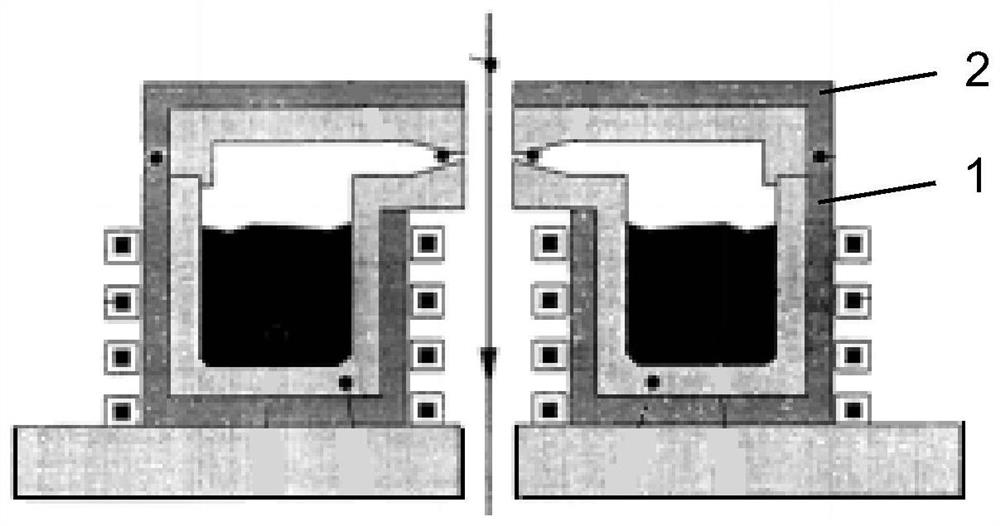
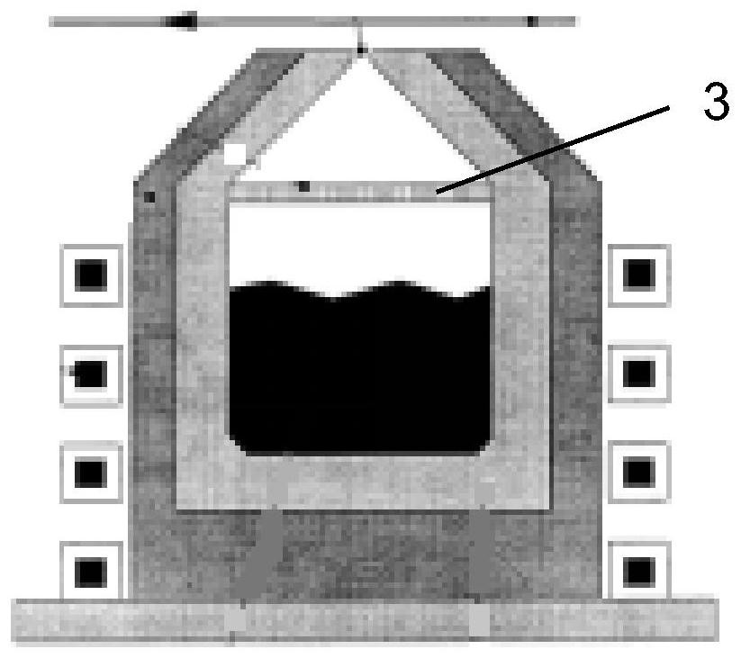
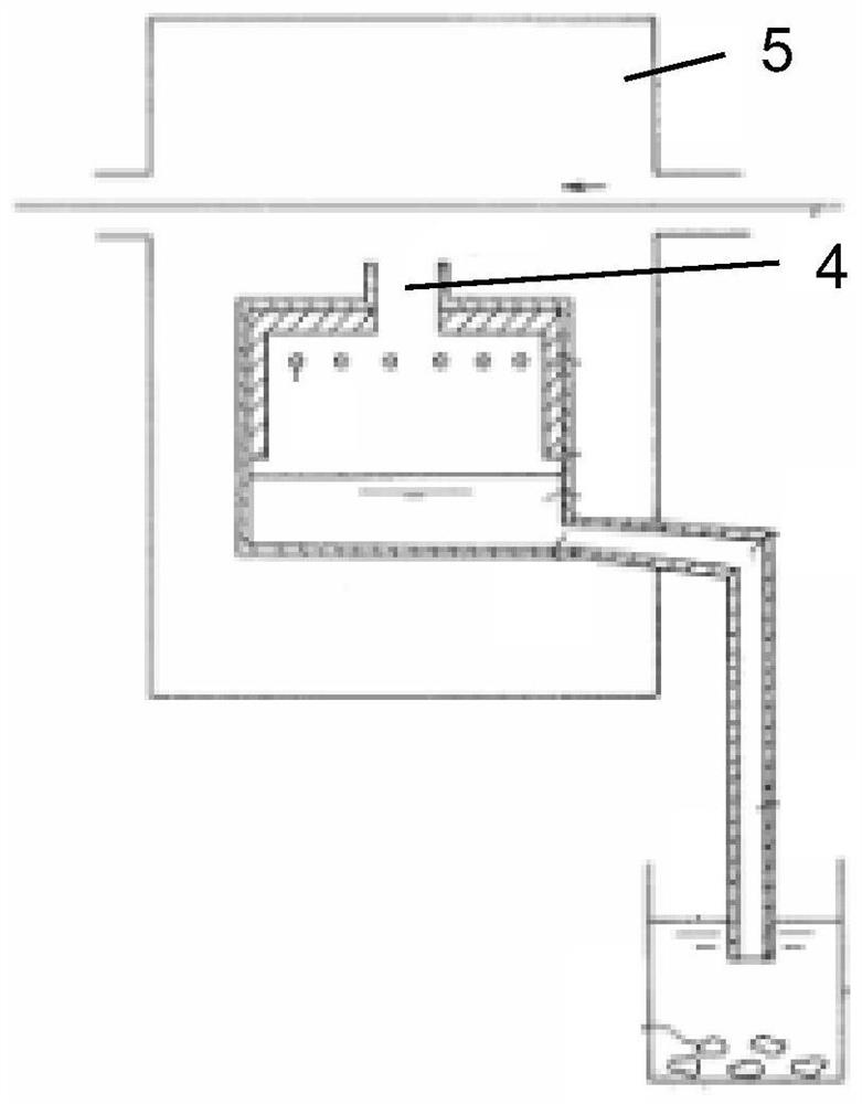
[0059] Zinc is evaporated on the surface of the steel plate 100, the width of the steel plate 100 is 1000mm, after cleaning and drying, the steel plate 100 is heated to 120°C. Use the induction heater 15 to evaporate the zinc, and control the power to make the zinc in the crucible 13 reach a pressure of 20000Pa. At this time, the pressure regulating valve 18 is in a closed state. When the gas pressure in the crucible 13 reaches 20000Pa, open the pressure regulating valve 18, and the metal The steam 22 enters the flow distribution box 17 through the steam pipe 16, the damper plate 20 adopts a rectangle, wherein V1 / V2=2, D=1mm, the voltage stabilizing plate 19 is a porous structure, S 孔隙总面积 / S 出口 =3, the internal pressure of the nozzle 21 is 5000Pa, the material of the nozzle 21 is graphite, and the outlet of the nozzle 21 adopts a slit shape, which is rectangular, S 出口 / S 入口 = 0.95.


PUM


Abstract

The invention discloses a vacuum coating device with a flow restraining type nozzle. The vacuum coating device comprises a crucible, an induction heater is arranged on the outer side of the crucible,a flow distribution box body is connected to the top of the crucible through a steam pipeline, a horizontal pressure stabilizing plate is arranged in the flow distribution box body, a nozzle is formedin the top of the flow distribution box body, and a pressure regulating valve is arranged on the steam pipeline; the pressure stabilizing plate is of a porous structure, a flow restraining plate is connected to the lower surface of the pressure stabilizing plate, the flow restraining plate is further arranged in the horizontal direction, and a gap is formed between the side edge of the flow restraining plate and the inner wall of the flow distribution box body; and a jet flow relaxation area is formed between the connecting position of the flow distribution box body and the steam pipeline andthe lower surface of the pressure stabilizing plate, and a jet flow acceleration area is formed between the upper surface of the pressure stabilizing plate and the connecting position of the flow distribution box body and the nozzle. When high-temperature steam makes contact with a low-temperature steel plate, uniform coatings are formed on the surface of the steel plate.

Description

technical field [0001] The invention relates to the technical field of vacuum coating, in particular to a vacuum coating device with a flow-restriction nozzle. Background technique [0002] Physical vapor deposition (PVD) refers to the process of heating the metal to be plated under vacuum conditions to deposit it on the substrate in a gaseous state to form a coating. According to different heating methods, it is divided into electric heating (resistance or induction) and electron beam gun heating (EBPVD). Vacuum coating, as a surface modification and coating process, has been widely used in electronics, glass, plastics and other industries. The main advantages of vacuum coating technology lie in its environmental protection, good coating performance and the diversity of materials that can be plated. The key to applying vacuum coating technology to continuous strip steel lies in the aspects of continuous coating production, large area, high speed, and large-scale production...

Claims


Application Information

Patent Timeline
Patent Type & Authority Applications(China)
IPC IPC(8): C23C14/26
CPCC23C14/26C23C14/243C23C14/16C23C14/562C23C14/24C23C14/228C23C14/56
Inventor 任三兵樊俊飞李山青张春伟金小礼
Owner BAOSHAN IRON & STEEL CO LTD
Why Eureka
Try Eureka