Boiler for chemical engineering production

A technology for chemical engineering and boilers, which is applied in the field of boilers for chemical engineering production, and can solve problems such as general heat utilization effect and reduced heat exchange effect

Active Publication Date: 2021-03-26
山东聚强绿洲生物科技有限公司
View PDF14 Cites 0 Cited by
  • Summary
  • Abstract
  • Description
  • Claims
  • Application Information

AI Technical Summary

Problems solved by technology

The boiler structure in traditional chemical engineering is relatively simple, and the heat utilization effect in the high-temperature flue gas generated by boiler combustion is general. Usually, the high-temperature flue gas is directly exchanged with the water heated in the boiler through the heat transfer medium, but as The temperature of the water in the boiler rises rapidly and keeps at a high temperature, and the heat transfer effect will also decrease, so there are certain limitations

Method used


Image

  • Boiler for chemical engineering production
  • Boiler for chemical engineering production
  • Boiler for chemical engineering production

Examples


Embodiment 1

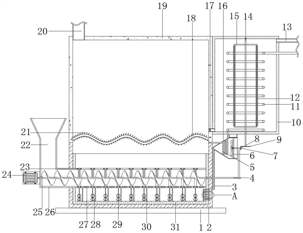
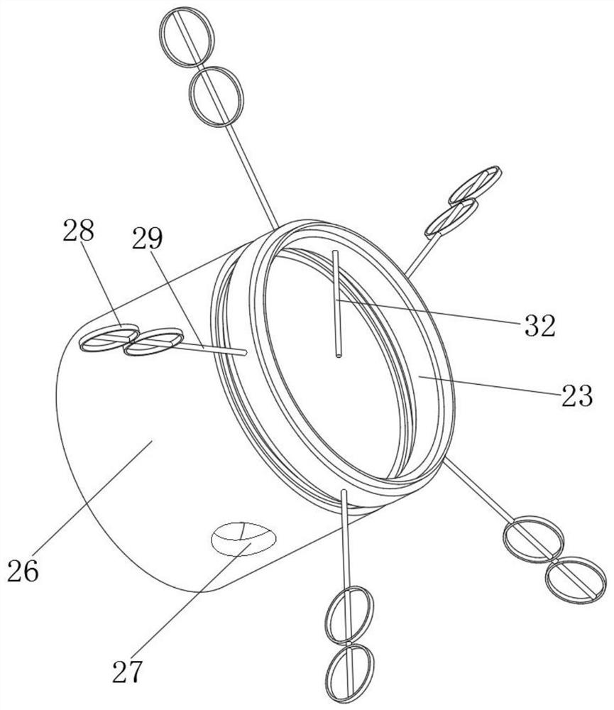
[0032] refer to Figure 1-6, a boiler for chemical engineering production, including a base plate 1, a combustion bottom 2 is welded on the top outer wall of the base plate 1, and a furnace body 19 is welded on the top of the combustion bottom 2, and a heat-resistant inner bottom is arranged on the inner bottom of the combustion bottom 2 Layer 31, the furnace body 19 and the opposite side of the combustion bottom 2 are welded with the same heat exchange bottom plate 18, and the section of the heat exchange bottom plate 18 is a waveform, and one end of the combustion bottom 2 is equipped with a feeding mechanism, and the feeding mechanism includes welding On the feeding end cylinder 26 of the combustion bottom 2, the opposite side of the feeding end cylinder 26 and the heat-resistant inner layer 21 are solidly welded with fixed struts 30 distributed equidistantly, and the feeding end cylinder 26 is opened with a cross section of the fixed struts 30. The ring slots of the distri...

Embodiment 2

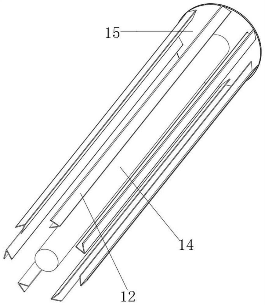
[0043] refer to Figure 7 , a boiler for chemical engineering production. Compared with Embodiment 1, this embodiment also includes that the opposite side of the driven end column 14 of the base plate and the corner piece 12 are welded with connecting pieces 39 distributed equidistantly, and the connecting piece 39 One end has a through hole, and the inner wall of the through hole is welded with a bucket-shaped end pipe 38; the connecting piece 39 and the bucket-shaped end pipe 38 arranged on the opposite side of the driven end column 14 and the angle piece 12 can effectively improve the angle. The liquid-repelling effect of the sheet 12, and the bucket-shaped end pipe 38 can produce a narrow pipe effect, further increasing the flow rate of the water liquid.

[0044] When the present invention is in use: the connecting piece 39 and the bucket-shaped end pipe 38 arranged on the opposite side of the driven end column 14 and the angle piece 12 can effectively improve the liquid-d...


PUM


Abstract

The invention belongs to the technical field of chemical engineering, and particularly relates to a boiler for chemical engineering production. Aiming at solving the problems that in traditional chemical engineering, a boiler is simple in structure, and the utilization effect of heat in high-temperature smoke generated by boiler combustion is common, the following scheme is provided. According tothe scheme, the boiler comprises a base plate, the outer wall of the top of the base plate is welded with a combustion bottom end, a furnace body is welded to the top end of the combustion bottom end,a heat-resisting inner layer is arranged at the inner bottom of the combustion bottom end, and the same heat exchange bottom plate is welded to the opposite sides of the furnace body and the combustion bottom end. According to the boiler, by means of an arranged driving motor, a material conveying rod can be driven to rotate; by means of a spiral pushing sheet, fuel is pushed, and the fuel is evenly added into the combustion bottom end through a discharging notch, so that the even feeding treatment is achieved; and by means of an arranged inner connecting rod, in the rotating process of the material conveying rod, a rotating inner end can be driven to rotate, and fuel can be effectively stirred through an outer stirring rod and a stirring ring on the outer wall of the material conveying rod.

Description

technical field [0001] The invention relates to the technical field of chemical engineering, in particular to a boiler for chemical engineering production. Background technique [0002] Chemical industry is the abbreviation of "chemical technology", "chemical industry", "chemical engineering" and so on. Any technology that uses chemical methods to change the composition and structure of substances or to synthesize new substances belongs to chemical production technology, that is, chemical technology, and the resulting products are called chemicals or chemical products. At first, what produce this series products is handicraft workshop, develops into factory later, and has gradually formed specific production industry, namely a chemical industry. Chemical engineering is a science that studies the general laws of the production process of chemical products. The relationship between human beings and chemical industry is very close, and some chemical products play an epoch-mak...

Claims


Application Information

Patent Timeline
Patent Type & Authority Applications(China)
IPC IPC(8): F24H1/34F24H9/18F23K3/10F23J15/06F23L5/02F23L15/00
CPCF23J15/06F23K3/10F23L5/02F23L15/00F24H1/34F24H9/1845Y02E20/34
Inventor 魏毅
Owner 山东聚强绿洲生物科技有限公司
Why Eureka
Try Eureka