Microbial fermentation equipment for sludge treatment

A technology of microbial fermentation and sludge treatment, applied in the direction of biological sludge treatment, etc., can solve the problems such as the inability to mix the sludge evenly, the sludge is not effectively fermented, etc., and achieve the effect of uniform fermentation treatment.

Pending Publication Date: 2021-09-24
王翠莲
View PDF6 Cites 0 Cited by
  • Summary
  • Abstract
  • Description
  • Claims
  • Application Information

AI Technical Summary

Problems solved by technology

[0004] Aiming at the deficiencies in the prior art, the purpose of the present invention is to provide a microbial fermentation equipment for sludge treatment, to solve the problem in the prior art when using aerobic fermentation equipment to ferment the microorganisms in the sludge. When the tank is stirred, it is a single stirring, which cannot make the sludge evenly mixed with each other, resulting in the defect that some sludge is not effectively fermented

Method used


Image

  • Microbial fermentation equipment for sludge treatment
  • Microbial fermentation equipment for sludge treatment
  • Microbial fermentation equipment for sludge treatment

Examples


no. 1 example

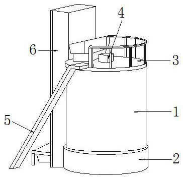
[0027] Such as Figure 1-Figure 3 As shown, the present invention provides a kind of technical scheme of microbial fermentation equipment for sludge treatment:

[0028] Such as Figure 1-Figure 2 As shown, a microbial fermentation equipment for sludge treatment, its structure includes a fermentation tank 1, a power drive chamber 2, a heat insulation cover 3, a uniform stirring device 4, an escalator 5, and a feeding rack 6. The power drive chamber 2 Installed on the lower surface of the fermenter 1, the heat insulating cover 3 is arranged on the upper surface of the fermenter 1, the uniform stirring device 4 is arranged inside the fermenter 1, and the top end is exposed to the air through the heat insulating cover 3, The end of the uniform stirring device 4 located inside the fermenter 1 is matched with the power drive chamber 2, the escalator 5 is inclined to match the fermenter 1, and the feeding rack 6 is vertically installed on the left side of the fermenter 1. On the ot...

no. 2 example

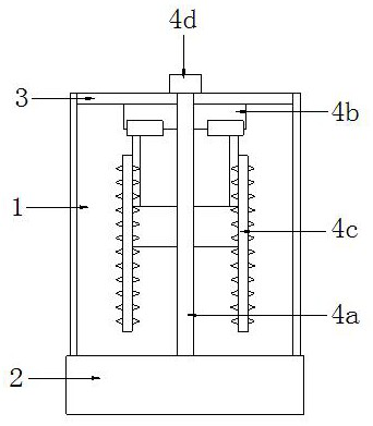
[0038] Such as Figure 4 As shown, the present invention provides a kind of technical scheme of microbial fermentation equipment for sludge treatment:

[0039] Such as Figure 4 As shown, a microbial fermentation equipment for sludge treatment, its structure includes that the inside of the rotating rod 4a is a hollow structure, which is respectively matched with the air flow box 4d and the oxygen filling part 4c1, and the air flow inside the air flow box 4d is outward flow.

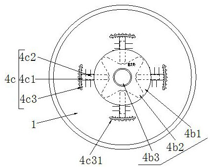
[0040] Such as Figure 4 As shown, the oxygen charging part 4c1 includes a shaft plate 4c11, a limit spring 4c12, a permeation hole 4c13, and a scraper rod 4c14. The shaft plate 4c11 is welded through the rotating rod 4a. Inside the plate 4c11, the penetration holes 4c13 are densely distributed on the surface of the shaft plate 4c11 and are an integrated structure, and the scraper rods 4c14 are distributed on the outer surface of the shaft plate 4c11 and connected vertically, which is beneficial to rea...


PUM


Abstract

The invention discloses microbial fermentation equipment for sludge treatment. The microbial fermentation equipment structurally comprises a fermentation tank, a power driving chamber, a heat insulation cover plate, a uniform stirring device, a ladder and a feeding frame. The invention has the beneficial effects that through cooperation of a limiting structure and the material overturning mechanism, under the structural action of a special-shaped wheel, the material overturning mechanism is pushed back and forth while rotating, so sludge in the fermentation tank is effectively overturned, so that the problems that a traditional fermentation tank is single in stirring during stirring is prevented, sludge cannot be uniformly mixed with each other, and therefore, part of sludge is not effectively fermented are solved. In addition, the conical blocks arranged on the surfaces of the material pushing arc plates are matched, so caked sludge can be mashed in the back-and-forth moving process, and maximum effective fermentation is further achieved.

Description

technical field [0001] The invention relates to the field of sludge treatment, in particular to a microbial fermentation equipment for sludge treatment. Background technique [0002] Sludge is a by-product produced in the process of sewage treatment, and it has the bacteria micelles formed by various microorganisms and various organic and inorganic substances adsorbed (Smith, 2009). At the same time, sludge also contains a large number of pathogenic bacteria, parasites, pathogenic microorganisms, and heavy metals such as arsenic, copper, chromium, mercury, and toxic and harmful substances that are difficult to degrade such as dioxins (Zhou Lixiang et al., 2000). [0003] When aerobic fermentation equipment is used to ferment the microorganisms in the sludge, the traditional fermentation tank is stirred in a single way, which cannot make the sludge evenly mixed with each other, resulting in some The sludge has not been effectively fermented. Contents of the invention [0...

Claims


Application Information

Patent Timeline
IPC IPC(8): C02F11/02
CPCC02F11/02
Inventor 王翠莲
Owner 王翠莲
Why Eureka
Try Eureka