Agricultural airing device
The technology of a drying device and a pushing device is applied in the field of drying, which can solve the problems of reducing storage space and not considering the accumulation of crops on the drying platform.
- Summary
- Abstract
- Description
- Claims
- Application Information
AI Technical Summary
Problems solved by technology
Method used
Image
Examples
Embodiment 1
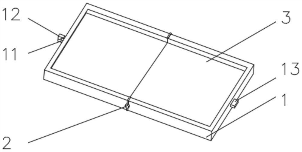
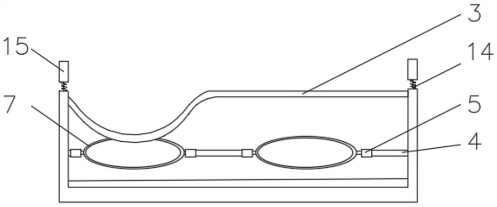
[0033] see Figure 1-2 , the present invention provides a technical solution: an agricultural drying device, comprising an outer frame 1, the outer frame 1 is symmetrically installed, the outer frame 1 is rotationally connected by a rotating rod 2, the inner wall of the outer frame 1 is fixedly connected with an elastic net 3, the outer frame The inner wall of 1 is equipped with a fixed rod 4 near the position of the elastic net 3, and one side of the fixed rod 4 is sleeved with a sliding bearing 5.
[0034] One side of the outer frame 1 is fixedly connected with a connecting rod 11 , the end of the connecting rod 11 away from the outer frame 1 is rotatably connected with a rotating block 12 , and the side of the outer frame 1 away from the connecting rod 11 is equipped with a locking block 13 .
[0035] A spring 14 is installed on the top of the outer frame 1 , and an extension frame 15 is fixedly connected to the end of the spring 14 away from the outer frame 1 .
[0036] W...
Embodiment 2
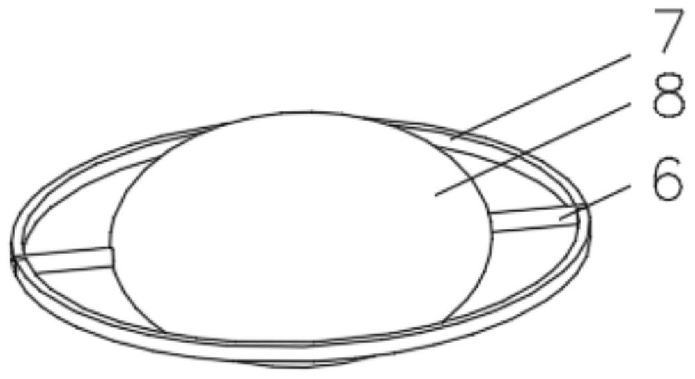
[0039] see Figure 1-5 , the present invention provides a technical solution: on the basis of Embodiment 1, a pusher 6 is installed on the outside of the sliding bearing 5, a ring 7 is installed on one side of the pusher 6, and an end of the pusher 6 away from the ring 7 is installed There are airbags8.
[0040] The pushing device 6 includes a push rod 61, one end of the push rod 61 is equipped with a piston handle 62, and the end of the push rod 61 close to the piston handle 62 is connected with an air outlet pipe 63, and the air outlet pipe 63 communicates with the air outlet of the air bag 8, and the push rod 61 is far away from the piston One end of the handle 62 is fixedly connected with a connection block 64, and one side of the connection block 64 is fixedly connected with a push plate 65 at a position away from the push rod 61. Groove 68, the outer side of connecting pipe 67 is fixedly connected with circular ring 7.
[0041] A universal roller 66 is mounted on the e...
Embodiment 3
[0044] see Figure 1-6 , the present invention provides a technical solution: on the basis of Embodiment 2, a bird repelling device 9 is installed on the end of the rotating rod 2 away from the outer frame 1, and the bird repelling device 9 includes a bottom column 91, and one side of the bottom column 91 is connected to the rotating Rod 2 is movably connected, and the top of bottom column 91 is connected with telescopic rod 92, and one end of telescopic rod 92 is provided with rolling bearing 93 far away from the position of bottom post 91, and the outer sleeve of rolling bearing 93 is provided with rotating frame 94, and one side of rotating frame 94 Connecting columns 95 are evenly installed, and one end of the connecting columns 95 is fixedly connected with a semicircular frame 96 .
[0045] A percussion device 10 is installed inside the bird repelling device 9, and the percussion device 10 includes an elastic rope 101, which is fixedly connected with the semicircular fram...
PUM
 Abstract
Description
Claims
Application Information
 - R&D
- Intellectual Property
- Life Sciences
- Materials
- Tech Scout
- Unparalleled Data Quality
- Higher Quality Content
- 60% Fewer Hallucinations
Browse by: Latest US Patents, China's latest patents, Technical Efficacy Thesaurus, Application Domain, Technology Topic, Popular Technical Reports.
© 2025 PatSnap. All rights reserved.Legal|Privacy policy|Modern Slavery Act Transparency Statement|Sitemap|About US| Contact US: help@patsnap.com


