
Lens refractive index measuring device and measuring method thereof

A measuring device and refractive index technology, applied in the field of optical measurement, can solve the problems of difficult detection, complicated operation, and high difficulty, and achieve the effect of fast detection and simple operation

Pending Publication Date: 2021-03-26
宁波法里奥光学科技发展有限公司
View PDF0 Cites 7 Cited by
  • Summary
  • Abstract
  • Description
  • Claims
  • Application Information

AI Technical Summary

Problems solved by technology

[0003] At present, there are mainly two detection methods for measuring the refractive index of finished lenses. One is to perform reverse calculation based on the focal power formula, that is, to use mechanical precision measurement methods to measure the curvature of the upper and lower surfaces, the central thickness, and the focal power of the lens. The focal length company calculates the refractive index of its test wavelength. This method is complicated and difficult to guarantee the measurement accuracy, and it is not suitable for the measurement of aspheric lenses; another method is to change the "environmental" refractive index method, that is, by changing the The refractive index of the upper and lower surfaces of the contact medium, such as placing the lens in a solution with a known refractive index, or attaching a flexible medium with a known refractive index to the upper and lower surfaces of the lens, respectively testing the optical power of the lens in air and in solution, according to The refractive index of the lens material can be calculated by the change of optical power and the refractive index of the solution. This method is also complicated to operate and difficult to detect.

Method used


Image

  • Lens refractive index measuring device and measuring method thereof
  • Lens refractive index measuring device and measuring method thereof
  • Lens refractive index measuring device and measuring method thereof

Examples


Embodiment Construction

[0037] For a better understanding of the application, various aspects of the application will be described in more detail with reference to the accompanying drawings. It should be understood that these detailed descriptions are descriptions of exemplary embodiments of the application only, and are not intended to limit the scope of the application in any way. Throughout the specification, the same reference numerals refer to the same elements.

[0038] It should be noted that in this specification, expressions such as first, second, etc. are only used to distinguish one feature from another, and do not represent any limitation on the features. Accordingly, first grooves discussed hereinafter may also be referred to as second grooves without departing from the teachings of the present application.

[0039] In the drawings, the thickness, size and shape of objects have been slightly exaggerated for convenience of illustration. The drawings are merely examples and are not stric...


PUM

PropertyMeasurementUnit
diameteraaaaaaaaaa
diameteraaaaaaaaaa
reflectanceaaaaaaaaaa

Abstract

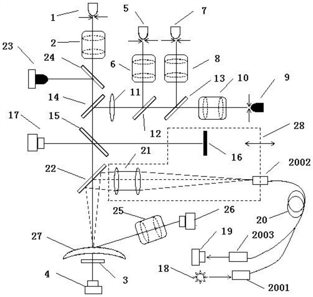
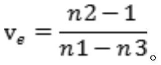
The invention discloses a lens refractive index measuring device which comprises a diopter measuring module, an optical thickness measuring module, a confocal reflection measuring module, a lens uppersurface curvature measuring module and a measured lens. The diopter measuring module is used for detecting the diopter of a measured lens, the confocal reflection measuring module is used for detecting the confocal reflection positions of the upper surface and the lower surface of the measured lens, the lens upper surface curvature measuring module is used for detecting the curvature of the uppersurface of the measured lens. Based on the structure, the refractive index of the lens can be measured according to the data in the above aspects without damaging the lens; The device is simple to operate and rapid in detection, and is suitable for refractive index measurement of common lenses, aspheric lenses, cylindrical lenses and other irregular surface lenses. The method for measuring the refractive index of the lens is simple to operate, rapid in detection and high in measurement precision.

Description

technical field [0001] The invention relates to the technical field of optical measurement, in particular to a lens refractive index measurement device and a measurement method thereof. Background technique [0002] The refractive index parameter is an important parameter index of the optical lens. In order to ensure the good imaging quality of the optical system, it is necessary to accurately measure the refractive index of the optical material. At present, the high-precision measurement of the refractive index of the optical glass material is carried out by the minimum deflection angle method. The minimum deflection angle method has high precision, a large wavelength range, and is a direct measurement. However, the premise of the minimum deflection angle test method is that a prism needs to be made for light refraction, and the angle of the prism needs to be accurately tested. Such a prism is difficult to manufacture. , the cycle is long; in addition, this method cannot te...

Claims


Application Information

Patent Timeline
Patent Type & Authority Applications(China)
IPC IPC(8): G01M11/02G01N21/41G01N21/45
CPCG01M11/0207G01M11/0235G01N21/41G01N21/45
Inventor 刘义兵孙昭刘力威
Owner 宁波法里奥光学科技发展有限公司
Learn More