
Transient observation device and method of nanoscopic multiphase interface based on laser action

A technology of laser action and observation device, applied in material excitation analysis, Raman scattering and other directions, can solve the problems of difficult capture and control of the position of the observed object, lack of effective experimental data support for molecular dynamics models, etc., to achieve excellent imaging contrast, The effect of stable optical path and improved resolution

Active Publication Date: 2021-11-02
PEKING UNIV
View PDF6 Cites 0 Cited by
  • Summary
  • Abstract
  • Description
  • Claims
  • Application Information

AI Technical Summary

Problems solved by technology

[0009] 5. In the transient observation process of nanoscopic multiphase interface, the position of the observed object is not easy to capture and control
[0010] 6. Various finite element models (such as NS equations of fluid mechanics) at the macro scale are often limited by the challenge that the continuity assumption does not hold true at the nano scale
[0011] Moreover, the nanoscopic multiphase interface molecular dynamics model lacks effective experimental data support, and the model can only be checked by static macroscopic physical quantities

Method used


Image

  • Transient observation device and method of nanoscopic multiphase interface based on laser action
  • Transient observation device and method of nanoscopic multiphase interface based on laser action
  • Transient observation device and method of nanoscopic multiphase interface based on laser action

Examples


Embodiment Construction

[0062] The present invention will be further described below in conjunction with the accompanying drawings to make those skilled in the art with reference to the specification.

[0063] It should be understood that, such as "having", "" ",", and "including" the terms used herein do not match the presence or addition of one or more other elements or combinations thereof.

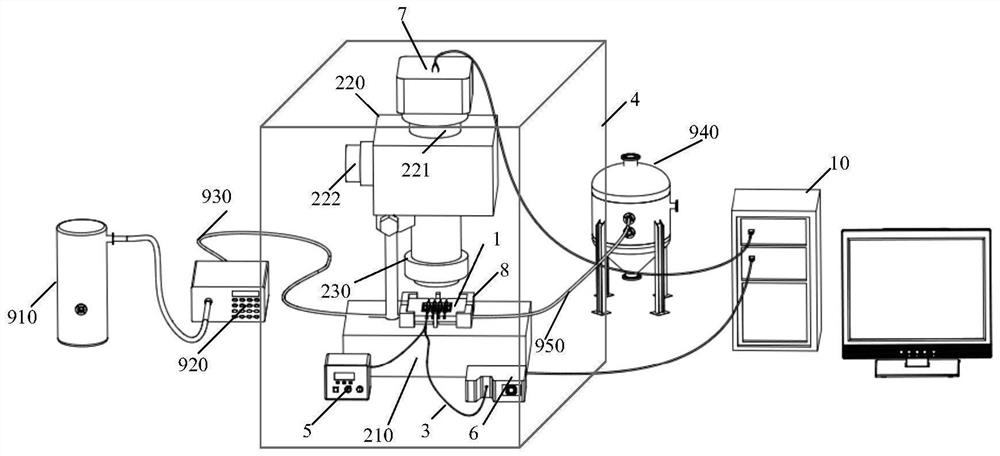
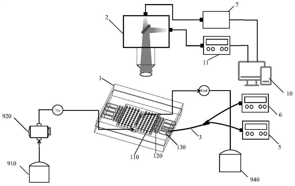
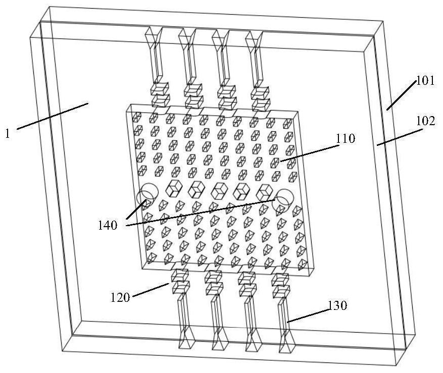
[0064] like Figure 1 to 3 As shown, the embodiment of the present invention provides a laser-based nano-phase interface transient observation device, including: microneedle fin heatup structural chip 1, placed on the microscopic detection scan platform 210, in the micro A microcapper array 110 is provided with a microcapper array 110, a lens structure 120 coupled to the microcapper array 110, and an optical fiber coupler 130 for connecting the end of the optical fiber 3, wherein in the micromolus array 110 The micro track between the columns includes a suspension solution containing gold nanoparticles, and placed...


PUM

PropertyMeasurementUnit
thicknessaaaaaaaaaa
wavelengthaaaaaaaaaa

Abstract

The invention discloses a nanoscopic multi-phase interface transient observation device based on laser action, which includes: a microneedle fin heat dissipation structure chip, which is placed on a microscopic detection scanning platform, and a microneedle fin heat dissipation structure chip is provided with a micro Column array, lens structure and fiber optic coupler, the suspension solution containing gold nanoparticles passes through the microfluidic channel of the microcolumn array, the microneedle fin heat dissipation structure chip and the microscopic detection scanning platform are placed in the cassette, and the double pulse width laser The emitted laser pulse is aligned with the lens structure under the action of the fiber coupler, and after focusing, it enters the micropillar array from the side and irradiates the gold nanoparticles in the suspension solution. In the dark field environment, the gold nanoparticles are formed after being irradiated by the laser pulse The transient state of the multiphase interface was observed. The device can perform high-resolution dark-field observation of the transient state of the nanoscopic multiphase interface generated in the microcolumn array, and can control the temperature of the microcolumn array. The invention also provides a method for transient observation of nanoscopic multi-phase interface based on laser action.

Description

Technical field [0001] The present invention belongs to the field of microscopic scale observations. More specifically, the present invention relates to a laser-based nano multiphase interface transient observation apparatus and a method thereof. Background technique [0002] The noble metal nanoparticles can become an ideal nano-heat source when the plasma resonance wavelength is emitted. A large amount of energy of femtosecond laser pulses can produce strong, short and limited temperature surround around the illuminated plasma nanoparticles, which ultimately result in a short bubble-shaped core. The first application of the plasma shot (MBS), including surface MB on the metal film, as an effective lens of surface plasma waves in the microfluidic environment. In this configuration, the plasma resonance of the nanoparticle assembly is about 530 nm. When such a system is localized under this wavelength, the effective light absorbing occurs on the glass-water interface of the nanop...

Claims


Application Information

Patent Timeline
Patent Type & Authority Patents(China)
IPC IPC(8): G01N21/65
CPCG01N21/65
Inventor 王振宇孙旖璠李伟刘宗玺
Owner PEKING UNIV
Learn More