Non-destructive detection method for pollutant components on surface of part

A non-destructive detection and component technology, applied in the detection field, can solve the problem that metal pollutants cannot be detected

Pending Publication Date: 2021-03-26
上海富乐德智能科技发展有限公司
View PDF5 Cites 3 Cited by
  • Summary
  • Abstract
  • Description
  • Claims
  • Application Information

AI Technical Summary

Problems solved by technology

Although this method can be used for non-destructive surface contamination testing of components, the contaminants it detects often require sufficient response to Raman spectroscopy
Since Raman spectroscopy is a molecular spectrum, this method cannot detect metal pollutants without molecular structure

Method used


Image

  • Non-destructive detection method for pollutant components on surface of part
  • Non-destructive detection method for pollutant components on surface of part
  • Non-destructive detection method for pollutant components on surface of part

Examples


specific Embodiment 1

[0049] It is suitable for the surface contamination analysis of an alumina ceramic ring component.

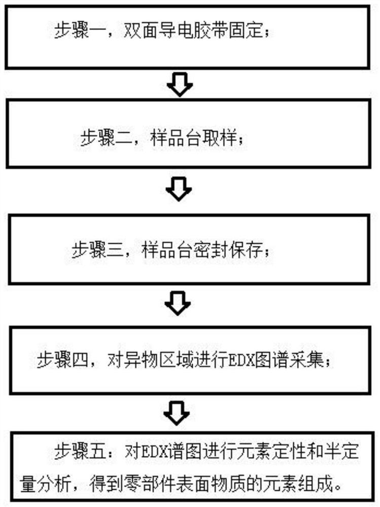
[0050] A method for non-destructive detection of pollutant components on the surface of parts, specifically comprising the following steps:

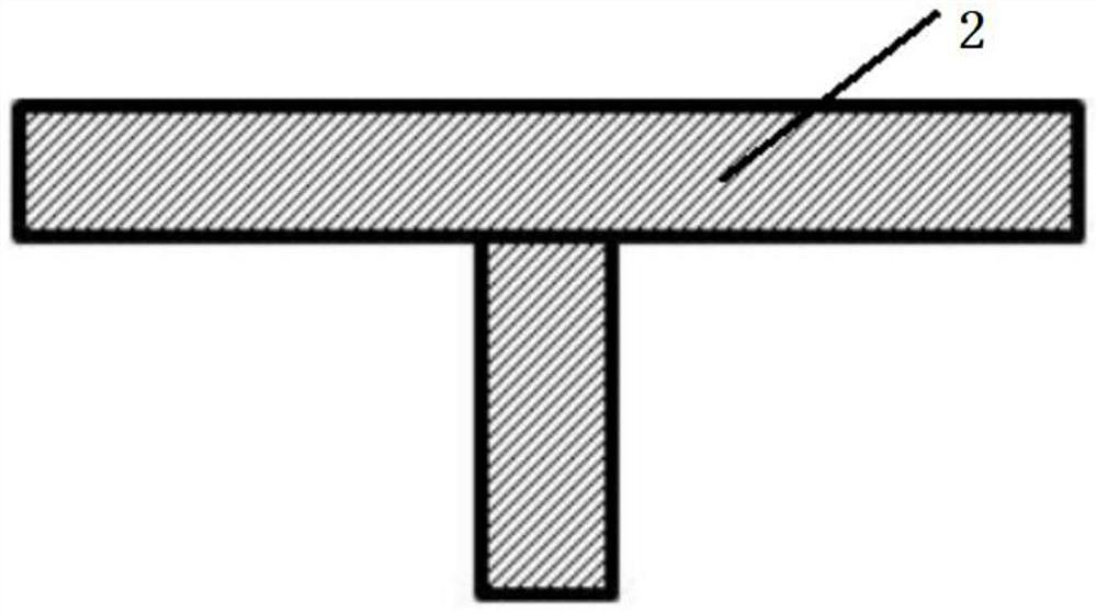
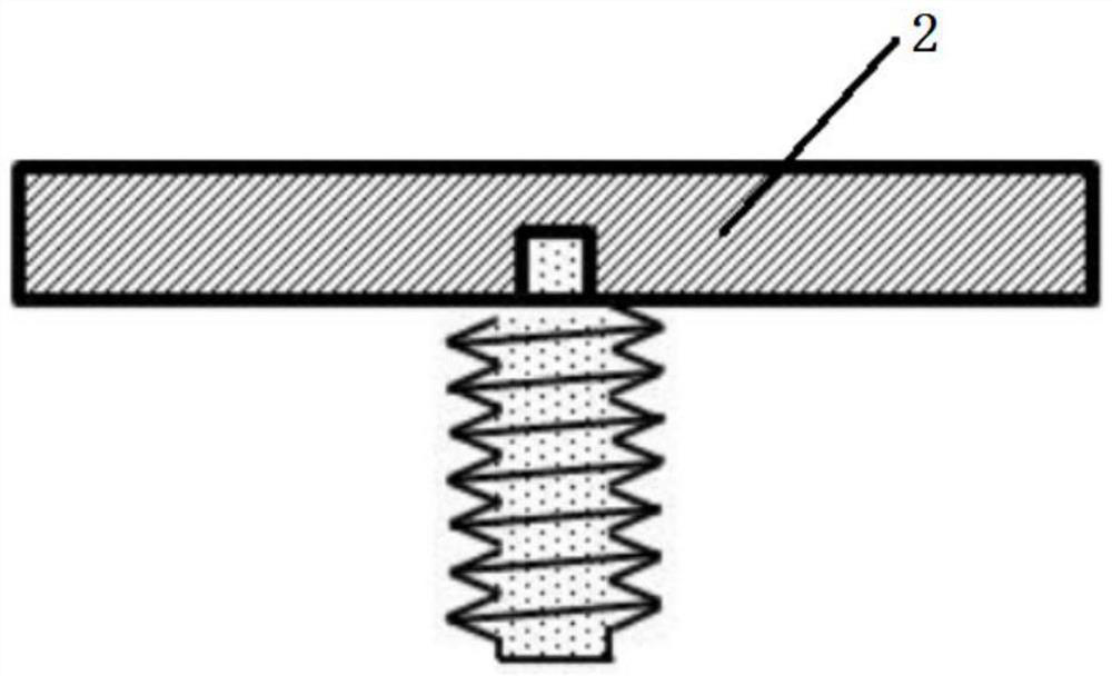
[0051] Step 1: Lay double-sided conductive tape on the sample stage of the scanning electron microscope; the bottom of the sample stage is provided with internal threads;

[0052] The sample stage is 30mm in diameter and 6mm in height.

[0053] The conductive adhesive is a double-sided conductive carbon tape with a width of 8mm, and the tape base is high-purity aluminum foil.

[0054] Step 2: Connect the threaded rod to the internal thread plane sample stage, peel off the protective strip on the conductive tape, and hold the threaded rod to adhere the front of the sample stage with the conductive tape to the surface area of ​​the ceramic ring component to be tested.

[0055] Step 3: After the sample stage adheres to the surface of the a...

specific Embodiment 2

[0062] A surface contamination analysis of yttria-coated chamber components.

[0063] A method for non-destructive detection of pollutant components on the surface of parts, characterized in that it comprises the steps of:

[0064] Step 1: Lay double-sided conductive tape on the sample stage of the scanning electron microscope; the bottom of the sample stage is provided with internal threads;

[0065] The sample stage is 15mm in diameter and 6mm in height. The conductive adhesive is a double-sided conductive carbon tape with a width of 8mm, and the tape base is high-purity aluminum foil.

[0066] Step 2: Connect the threaded rod with the internal thread plane sample stage, remove the protective strip on the conductive tape, and adhere the front of the sample stage with the conductive tape on the surface area of ​​the cavity part to be tested.

[0067] Step 3: After the sample stage adheres to the surface of the cavity parts for two minutes, remove the sample stage, quickly p...


PUM

PropertyMeasurementUnit
diameteraaaaaaaaaa
heightaaaaaaaaaa

Abstract

The invention relates to the technical field of detection. The invention discloses a non-destructive detection method for pollutant components on the surface of a part. The method comprises the following steps: 1, fixing a double-sided conductive adhesive tape, and paving a double-sided conductive adhesive tape on a sample table of a scanning electron microscope; 2, sampling on a sample table, tearing off the protective strip on the double-sided conductive adhesive tape, and adhering the surface area of the to-be-tested part to the double-sided conductive adhesive on the sample table; 3, sealing and storing the sample table, taking down the sample table, putting the sample table into a clean sample table tube, fixing the sample table tube, and sealing the sample table tube; 4, performing EDX atlas acquisition on the foreign matter area, taking down the sample table from the sample table tube, putting the sample table into a sample cabin of a scanning electron microscope, observing foreign matters adhered to the double-sided conductive adhesive by using the scanning electron microscope, and performing EDX atlas acquisition on a foreign matter area by using an energy dispersive spectrometer; 5, carrying out element qualitative and semi-quantitative analysis on the EDX spectrogram to obtain the element composition of the substances on the surface of the part.

Description

technical field [0001] The invention relates to the technical field of detection, in particular to a detection method of pollutant components. Background technique [0002] In precision manufacturing processes such as semiconductor and display panel manufacturing, parts of key manufacturing equipment (such as lithography equipment, etching equipment, and thin film deposition equipment) will be polluted by particulate matter during long-term use, or be in contact with process materials (such as special Gas) undergoes a chemical reaction to form a surface contamination layer, which needs to be cleaned and regenerated before reuse. The detection of the components of pollutants on the surface of parts can help to develop a more targeted cleaning and regeneration process, effectively remove surface pollutants, and reduce the loss of parts. Moreover, the analysis of the pollutant components on the surface of parts can provide important supporting data for the failure analysis of ...

Claims


Application Information

Patent Timeline
Patent Type & Authority Applications(China)
IPC IPC(8): G01N23/2251
CPCG01N23/2251
Inventor 李文阁贺贤汉侯晓晨张正伟蒋立峰
Owner 上海富乐德智能科技发展有限公司
Why Eureka
Try Eureka