
Reciprocating forming equipment for fuel cell metal polar plate

A metal plate and forming equipment technology, applied in metal processing equipment, metal rolling, metal rolling, etc., can solve the problems affecting the life and safety of the stack, inaccurate hole shape alignment, poor consistency, etc., to achieve The effect of improving the forming accuracy of the pole plate, reducing the damage of the pole plate, and improving the filling performance

Active Publication Date: 2021-03-30
TAIYUAN UNIVERSITY OF SCIENCE AND TECHNOLOGY
View PDF13 Cites 0 Cited by
  • Summary
  • Abstract
  • Description
  • Claims
  • Application Information

AI Technical Summary

Problems solved by technology

Defects such as plate manufacturing deviations and defective products can easily cause stack failure, and its quality directly affects the output power and service life of the fuel cell stack
However, there are problems of poor consistency and low processing efficiency in the use of micro-forming technology for the electrode plate, and there are defects such as wrinkling, cracks, and uneven thinning in the high-aspect-ratio flow channel processed by traditional processes such as stamping, which affect the life and safety of the stack. Seriously restricting the industrial production of metal plates
The existing metal plate processing method based on roll forming will cause problems such as cracking, inaccurate hole shape alignment, and inaccurate processing and forming during high-precision processing, and the springback phenomenon is more prominent

Method used


Image

  • Reciprocating forming equipment for fuel cell metal polar plate
  • Reciprocating forming equipment for fuel cell metal polar plate
  • Reciprocating forming equipment for fuel cell metal polar plate

Examples


Embodiment Construction

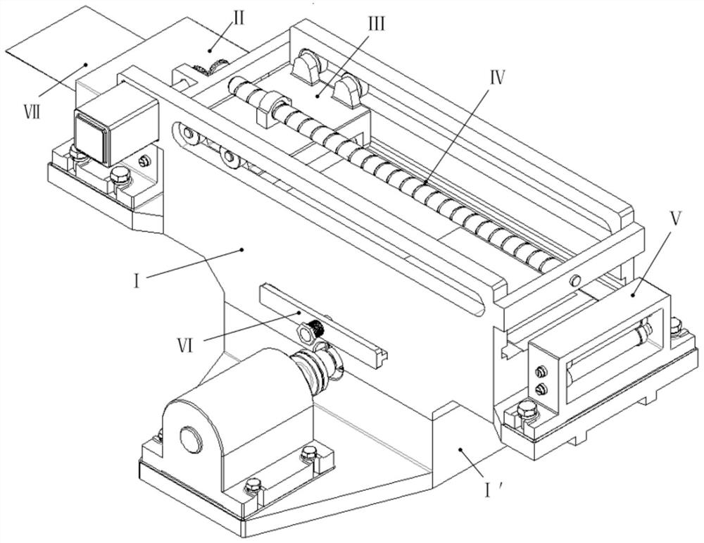
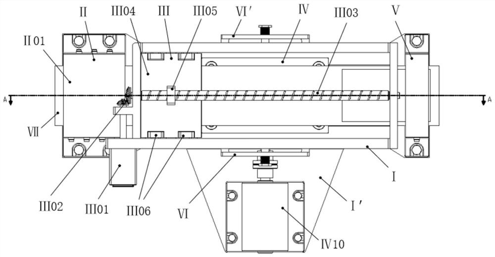
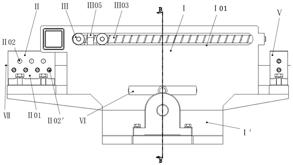
[0016] A fuel cell metal plate reciprocating forming equipment, such as figure 1 , 2 , 3, 4, and 5, when the metal blank needs to be processed and produced, the metal forming blank VII is straightened by the pole plate straightening device II, and then enters the forming station of the plane hard mold IV01 to stop, and the plane hard mold moves The motor Ⅳ10 drives the eccentric on the eccentric shaft Ⅳ05 to rotate upwards by 180°, pushing the flat dura mater Ⅳ01 to move upwards to the forming station; The nut Ⅵ02 is powered off, and the compression spring Ⅵ04 pushes the U-shaped limit pin Ⅵ01 to move into the frame, and the support platform Ⅳ03 is stuck, so that the flat dura mater Ⅳ01 stops at the forming station; the plate moving forming mechanism Ⅲ is installed on the The mobile forming motor Ⅲ01 on the upper left end of the upper frame Ⅰ drives the lead screw Ⅲ03 installed in the upper frame Ⅰ through the bevel gear Ⅲ02, and the lead screw Ⅲ03 drives the mobile platform ...


PUM


Abstract

The invention discloses reciprocating forming equipment for a fuel cell metal polar plate, and belongs to the technical field of cell metal polar plate forming equipment. The equipment is characterized by comprising a straightening device, a movable forming mechanism, a plane hard die transmission mechanism, a tensioning device and a limiting mechanism. A blank enters a rack, firstly enters the polar plate straightening device and then enters a forming station to be stopped, a plane hard die moving motor drives a plane hard die to move upwards to the forming station through eccentric shaft transmission, the limiting mechanism works simultaneously, a compression spring pushes a U-shaped limiting pin to move inwards to clamp a supporting platform, a moving platform rolls and forms the polarplate from an initial position along an advancing direction of the polar plate, after rolling, an electromagnet nut of the limiting mechanism is electrified to attract the U-shaped limiting pin to return to the initial position, and the plane hard die moving motor drives the eccentricity on the eccentric shaft to rotate downwards, so that the plane hard die is separated from the forming station. The equipment has the advantages that the shape filling performance of soft die forming and the forming accuracy of the polar plate are improved, resilience after forming is reduced, and the requirement for continuous production is met.

Description

technical field [0001] The invention relates to a fuel cell metal pole plate reciprocating forming equipment, which belongs to the technical field of battery metal pole plate forming equipment. Background technique [0002] As the core component of the fuel cell, the metal bipolar plate is composed of cathode and anode plates. The plate has a complex flow field structure and plays the functions of distributing water and gas, supporting the stack, and collecting current. Defects such as plate manufacturing deviations and defective products can easily cause stack failure, and its quality directly affects the output power and service life of the fuel cell stack. However, there are problems of poor consistency and low processing efficiency in the use of micro-forming technology for the electrode plate, and there are defects such as wrinkling, cracks, and uneven thinning in the high-aspect-ratio flow channel processed by traditional processes such as stamping, which affect the li...

Claims


Application Information

Patent Timeline
Patent Type & Authority Applications(China)
IPC IPC(8): B21B1/38B21B13/02B21B27/03B21B39/02B21B39/14
CPCB21B1/38B21B13/023B21B27/037B21B39/02B21B39/14B21B2001/386Y02E60/50
Inventor 赵富强段鑫锋张彦雷范晓宇黄庆学杨柳
Owner TAIYUAN UNIVERSITY OF SCIENCE AND TECHNOLOGY
Learn More