
Centerless through type superfinishing machine guide roller adjusting device and method

An adjustment device and a technology of a superfinishing machine, applied in the field of mechanical processing and manufacturing, can solve the problems of inconvenient operation, low precision, poor consistency, etc., and achieve the effects of improving adjustment accuracy and consistency, ensuring adjustment accuracy and high adjustment accuracy.

Pending Publication Date: 2021-03-30
HENAN UNIV OF SCI & TECH
View PDF0 Cites 0 Cited by
  • Summary
  • Abstract
  • Description
  • Claims
  • Application Information

AI Technical Summary

Problems solved by technology

Since the contact surface between the whetstone and the workpiece is a curved surface, it is difficult to judge whether the front and rear positions of the two contact are appropriate, and it is difficult to judge accurately by the operator's naked eyes, and the naked eye observation and adjustment operation cannot be carried out at the same time. Therefore, this adjustment method has low precision. Poor consistency and inconvenient operation
In addition, the measurement of the center distance of the front and rear guide rollers by this method is carried out by measuring tools such as vernier calipers or feeler gauges, which is not convenient
With the continuous improvement of superfinishing requirements, the adjustment accuracy and operation convenience of the guide rollers of existing devices and methods have been difficult to meet the requirements of modern high-precision parts superfinishing

Method used


Image

  • Centerless through type superfinishing machine guide roller adjusting device and method
  • Centerless through type superfinishing machine guide roller adjusting device and method
  • Centerless through type superfinishing machine guide roller adjusting device and method

Examples


Embodiment Construction

[0031] In the following, the present invention will be specifically described through exemplary embodiments. It should be understood, however, that elements, structures and characteristics of one embodiment may be beneficially incorporated in other embodiments without further recitation.

[0032] It should be noted that unless otherwise defined, the technical terms or scientific terms used herein shall have the usual meanings understood by those with ordinary skill in the field of the present invention. Words such as "a", "an" or "the" used in the specification and claims of the patent application of the present invention do not express a limitation on quantity, but mean that there is at least one. Words such as "comprises" or "comprises" and similar terms indicate that the elements or items preceded by "comprises" or "comprises" include the elements or items listed after "comprises" or "comprises" and their equivalents, but do not exclude other component or object.

[0033]...


PUM


Abstract

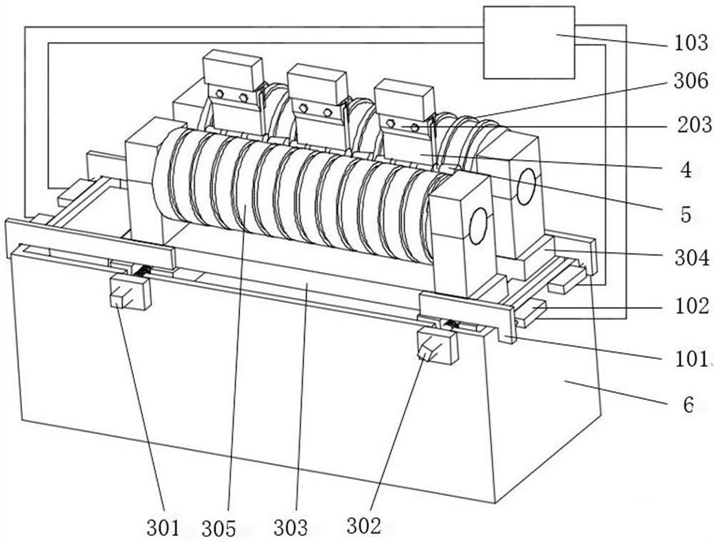
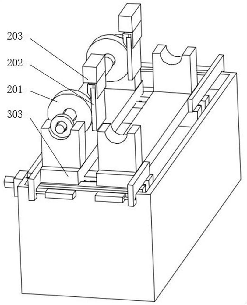
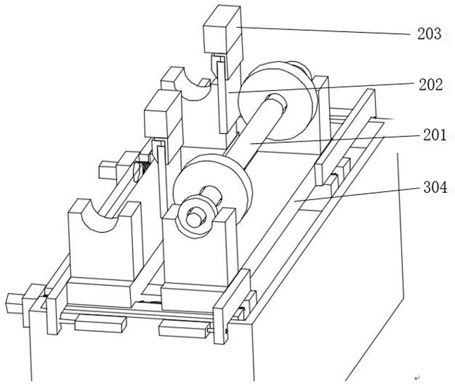
A centerless through type superfinishing machine guide roller adjusting device comprises a transmission assembly, a position sensing and displaying assembly and a calibration assembly; a displacementsensor in the position sensing and displaying assembly detects the position of a sensor pressing plate and outputs the position to a display module for displaying; the calibration assembly is composedof a calibration rod kit, a calibration flat plate and an oilstone clamp; the calibration flat plate is clamped in the oilstone clamp and used for representing the position of an oilstone; the calibration rod kit is composed of a calibration rod, a supporting disc and a standard diameter disc; and position data of a front guide roller and a back guide roller are calibrated through the standard diameter disc and the calibration flat plate. The guide roller position data are calculated and used as a design value on the basis of the calibrated reference position according to the adjustment requirement of the workpiece relative to the front and back positions of the oilstone and the adjustment requirement of the center distance between the front and back guide rollers; and the front and backpositions of the front and back guide rollers are adjusted, when the data displayed by the display module are consistent with the design values, the adjustment is considered to be in place. The devicehas the advantages of high adjusting precision, good consistency and rapidness and convenience in adjustment.

Description

technical field [0001] The invention relates to the field of mechanical processing and manufacturing, in particular to a device and method for adjusting guide rollers of a centerless penetrating superfinishing machine. Background technique [0002] At present, the centerless through-type superfinishing machine is a high-efficiency superfinishing machine tool. Its working method is that a pair of guide rollers configured front and rear for fixed axis rotation support the workpiece, and drive the workpiece to rotate from right to left while rotating. Or penetrating motion from left to right; a row of oil stones arranged along the penetrating direction of the workpiece is floatingly pressed on the workpiece with a certain pressure from directly above, and is driven by the oscillating device to perform high-frequency small-amplitude linear reciprocating motion, and continuously Superfinishing of through-pass workpieces. The centerless through-type superfinishing machine used fo...

Claims


Application Information

Patent Timeline
IPC IPC(8): B24B35/00B24B55/00B24B49/00
CPCB24B35/00B24B49/00B24B55/00
Inventor 高作斌
Owner HENAN UNIV OF SCI & TECH
Learn More