Self-cleaning type glass product processing device

A technology for glass products and processing devices, which is applied to manufacturing tools, stone processing tools, stone processing equipment, etc., can solve the problems of reduced water flow, difficulty in realizing self-circulation of water flow, and long time required for filtration, and achieves high efficiency. Effect

Inactive Publication Date: 2021-03-30
江西昌浩实业有限公司
View PDF1 Cites 1 Cited by
  • Summary
  • Abstract
  • Description
  • Claims
  • Application Information

AI Technical Summary

Problems solved by technology

[0003] The existing patent No. CN108455837B proposes an automotive glass cutting device, which uses air extraction to clean debris and dust, but in the process of glass construction, a large number of splashing debris will be generated when the glass is in contact with a high-speed rotating hacksaw and powder, the cleaning range and intensity of the air extraction method are limited, resulting in poor cleaning effect and the inability to cool down the glass
[0004] However, most of the existing technologies use the method of washing glass products with water, which can not only cool down the glass products, but also take away the debris and powder produced in the cutting process by water, so as to avoid the problem of dust floating and polluting the environment. However, due to the finer powder during glass cutting, a filter plate with extremely small pores is required for filtration, and a filter plate with extremely small pores will greatly reduce the fluidity of the water flow, and the time required for filtration is extremely long, making the device difficult to realize. self-circulation of water flow

Method used


Image

  • Self-cleaning type glass product processing device
  • Self-cleaning type glass product processing device
  • Self-cleaning type glass product processing device

Examples


Embodiment 1

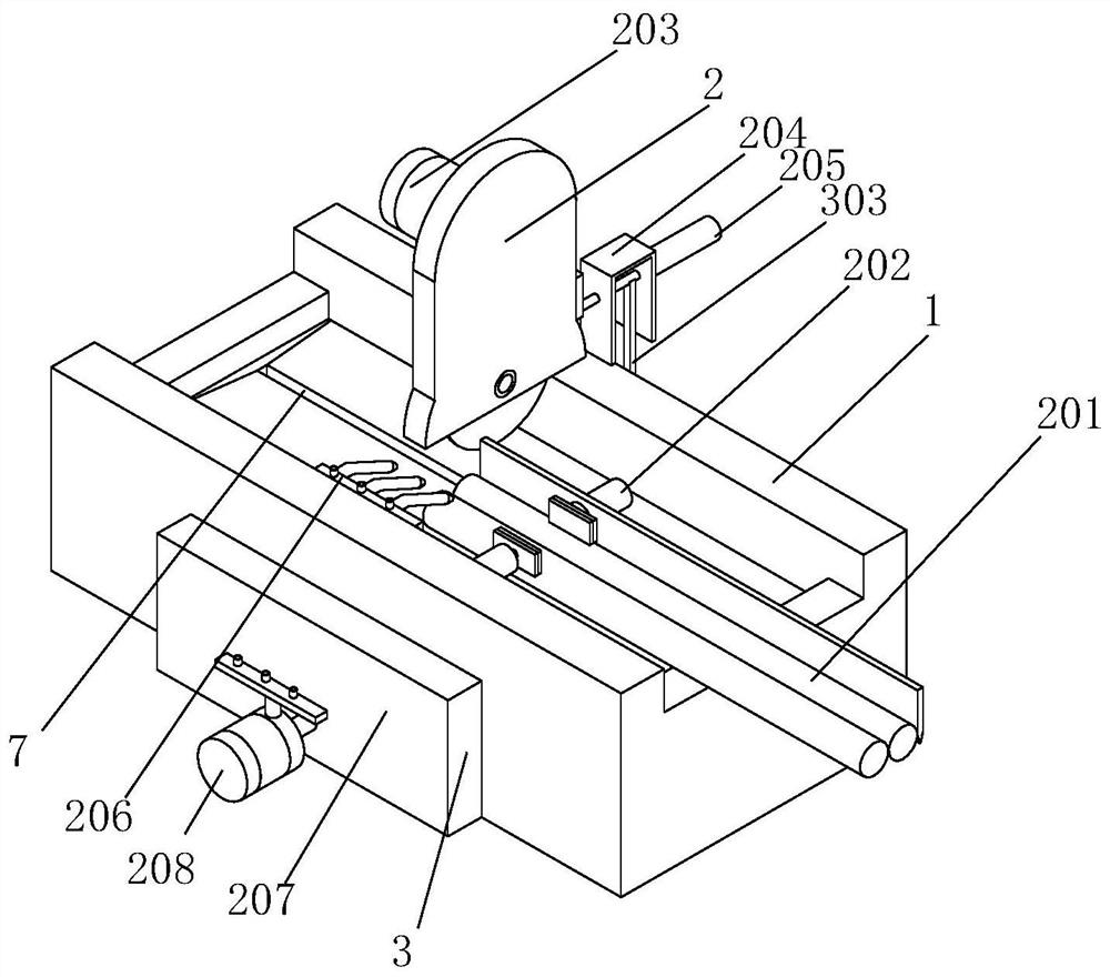
[0037] Example 1: Please refer to Figure 1-3 , a self-cleaning type glass product processing device, comprising a processing table 1, the top surface of the processing table 1 and the left and right sides are hollowed out, the inside of the processing table 1 is in a hollowed out state, the top surface of the processing table 1 is provided with a processing mechanism 2, and the processing A cleaning mechanism 3 is arranged inside the table 1, and the processing mechanism 2 includes a transmission table 201, a clamping mechanism 202 and a cutting mechanism 203. The transmission table 201 is fixedly installed on the right side of the top surface of the processing table 1, and the number of the clamping mechanisms 202 is two and They are respectively arranged on the processing table 1 and the transmission table 201 in an opposing state. The back side of the processing table 1 is fixedly connected with a fixed frame 204. The back side of the fixed frame 204 is fixedly equipped wit...

Embodiment 2

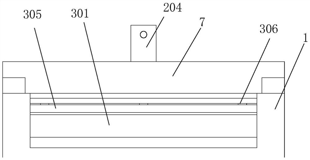
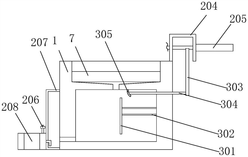
[0038] Embodiment 2: On the basis of Embodiment 1, please refer to Figure 4-7 The anti-blocking mechanism 4 includes a pneumatic cylinder 401, the front side of the connecting rod 304 is hollowed out, the middle part of the connecting rod 304 is in a cut state and is fixedly connected and communicated with the pneumatic cylinder 401, the inner wall of the pneumatic cylinder 401 is sleeved with a piston A402, and the front of the piston A402 The side is fixedly connected with a pull rod 404, the front end of the pull rod 404 is fixedly connected with the guide plate 305, the connecting rod 304 is fixedly connected with a magnetic ring 403 on the inner wall behind the piston A402, and the piston A402 is attracted by the magnetic force of the magnetic ring 403. When cutting larger glass products, the transmission shaft of the telescopic cylinder 205 needs to be extended slowly during the cutting process, so that the guide plate 305 will not approach the water flow immediately wit...

Embodiment 3

[0040] Embodiment three: on the basis of embodiment two, please refer to Figure 8-9 The water level detection mechanism 5 includes a water suction pipe 501 and a cylinder 502. The bottom surface of the connecting rod 304 is fixedly connected and communicated with the cylinder 502 at the position between the two air guide cylinders 405. The inner wall of the back of the processing table 1 is arranged and communicated with five vertically distributed The suction pipe 501 and the bottom end of the cylinder 502 are fixed and communicated with a suction pipe 501 through the liquid pipe 504. The inner wall of the cylinder 502 is fitted with a piston B503. Springs and baffles require high pressure for extraction and exhaust, so the air will be extracted and injected into the cylinder 502 first, and the extraction and injection of air in the cylinder 502 will drive the reciprocating sliding of the piston B503, and the piston B503 will slide upwards At the same time, the air or water ...


PUM


Abstract

The invention relates to the technical field of glass processing, and discloses a self-cleaning type glass product processing device which comprises a processing table. A processing mechanism is arranged on the top surface of the processing table, and a cleaning mechanism is arranged in the processing table. Through the arrangement of the cleaning mechanism, when a cutting step is started, water flow is automatically guided to a channel passing through a filter plate for filtering operation, so that chippings and powder removed through the water flow in the cutting step are filtered out, and the problems that the chippings and powder removed through the water flow are difficult to remove, and equipment is damaged due to the fact that the chippings and powder enter a water pump are solved;and guiding of the water flow is automatically stopped after the cutting step, and the water flow without the cleaning effect is guided to a channel without passing through the filter plate, so that the problem that the service life of the filter plate is greatly shortened due to continuous impact of the water flow on the filter plate is avoided, and the problem that water circulation cannot be achieved due to low water flow backflow efficiency due to the fact that the flow speed and flow of the water flow are reduced due to the fact that the powder needs to pass through the filter plate and holes of the filter plate are small are solved.

Description

technical field [0001] The invention relates to the technical field of glass processing, in particular to a self-cleaning glass product processing device. Background technique [0002] In the cutting process of glass products in the shape of some cylinders, most of them need to use a high-speed rotating hacksaw. When cutting with a high-speed rotating hacksaw, the glass will generate high temperature due to friction, and a large amount of heat will be generated due to high speed. Splashing debris and dust, how to clean up high temperature and debris and dust has become an urgent problem to be solved. [0003] The existing patent No. CN108455837B proposes an automotive glass cutting device, which uses air extraction to clean debris and dust, but in the process of glass construction, a large number of splashing debris will be generated when the glass is in contact with a high-speed rotating hacksaw And powder, the cleaning range and intensity of the air extraction method are ...

Claims


Application Information

Patent Timeline
Patent Type & Authority Applications(China)
IPC IPC(8): B28D1/22B28D7/02B28D7/04
CPCB28D1/22B28D7/02B28D7/04
Inventor 兰天
Owner 江西昌浩实业有限公司
Why Eureka
Try Eureka