Eureka AIR delivers breakthrough ideas for toughest innovation challenges, trusted by R&D personnel around the world.

Wastewater treatment device

A waste water treatment and waste water technology, applied in water/sewage treatment, water/sewage multi-stage treatment, water/sludge/sewage treatment, etc., can solve problems such as large ineffective loss, loss of effectiveness of purification components, and drop in pH value of water body , to achieve the effect of improving the effect

Active Publication Date: 2021-03-30
六合天地(武汉)环境有限公司
View PDF8 Cites 0 Cited by
  • Summary
  • Abstract
  • Description
  • Claims
  • Application Information

AI Technical Summary

Problems solved by technology

[0004] This technology is also divided into two types, one is to directly contact the discharge source of the discharge device with the water body, so that the generated ions, negative ions, electrons and water molecules and free radicals directly react; however, this method is likely to cause the pH value of the water body to drop rapidly , triggering a series of chemical reactions of free radicals, resulting in the formation of a large number of unfavorable by-products in the water body
[0005] The other is to electrolyze air through high-voltage discharge to generate gas containing ions, negative ions, ozone and other components, and then pass the gas through the water body for reaction; but in this method, the discharge source is far away from the liquid surface of the wastewater, and a gas pipeline is required for diversion and transportation , it is easy to cause the purification components contained in the gas to lose their effectiveness during the diversion process, and the ineffective loss during the transportation process is large, resulting in poor purification effect

Method used


Image

  • Wastewater treatment device
  • Wastewater treatment device
  • Wastewater treatment device

Examples


Embodiment Construction

[0028] The following will clearly and completely describe the technical solutions in the embodiments of the present invention in conjunction with the embodiments of the present invention. Obviously, the described embodiments are only part of the embodiments of the present invention, not all of them. Based on the implementation manners in the present invention, all other implementation manners obtained by persons of ordinary skill in the art without making creative efforts belong to the scope of protection of the present invention.

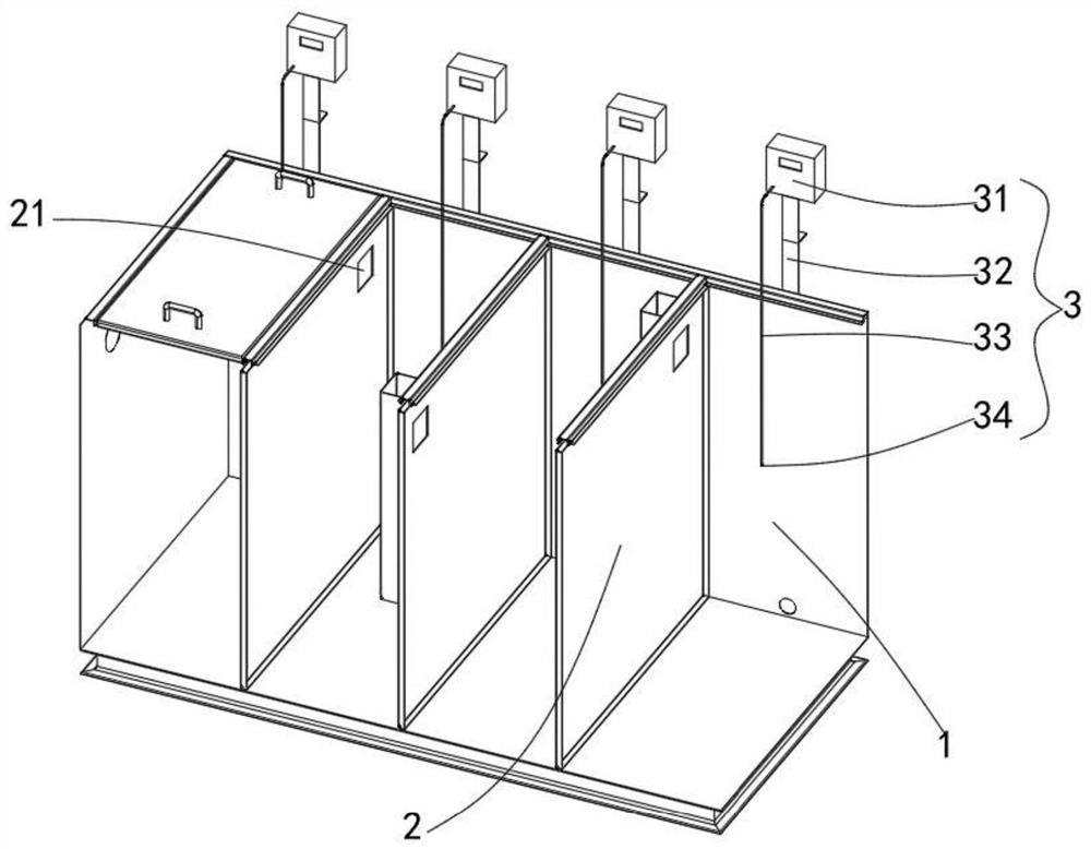
[0029] Such as figure 1 As shown, a waste water treatment device of the present invention includes a box body 1 with a cover, a separator 2, an electrolysis assembly 3, a floating assembly and a stirring mechanism.

[0030] Wherein, the two sides of the box body 1 with a cover that are not adjacent to each other are respectively provided with water inlets and outlets, and the box body 1 with a cover contains waste water.

[0031] The electrolytic ...


PUM


Abstract

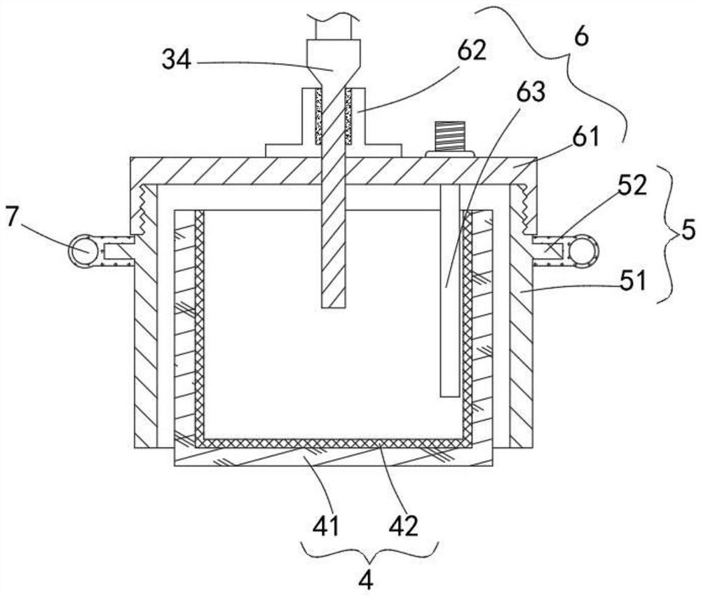
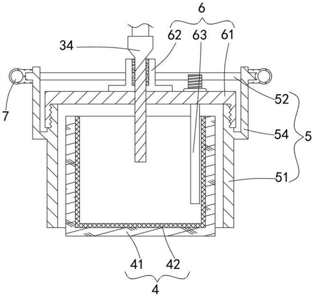
The invention provides a wastewater treatment device that comprises a box body with a cover, an electrolysis assembly and a floating assembly; wherein the electrolysis assembly comprises a discharge mechanism, a supporting rod, a wire and a spray point, the spray point is provided with a discharge end, the discharge end is inserted below the liquid level of wastewater, and the floating assembly isfixedly connected to the discharge end of the spray point; the floating assembly is provided with a cavity, the cavity is communicated with the waste water, the floating assembly isolates the discharge end of the spray point in the cavity, the discharge mechanism excites the spray point to discharge at the bottom end, and ion gas is generated in the cavity of the floating assembly in an air electrolysis mode to purify the waste water; the discharge end of the discharge needle is inserted below the liquid level of the wastewater, the floating assembly is arranged to isolate the discharge end in the cavity, and meanwhile, the cavity of the floating assembly is communicated with the wastewater, so that the discharge end cannot be directly contacted with the water body to cause lower pH valueof the water body; besides, the effective components generated by electrolyzing air at the discharge end can quickly contact a water body to generate a purification effect.

Description

technical field [0001] The invention relates to the technical field of wastewater treatment, in particular to a wastewater treatment device. Background technique [0002] The catering industry produces a large amount of wastewater during daily production and operation. At present, the traditional wastewater purification treatment process includes halogen, ultraviolet light and so on. Carcinogenic organic by-products are likely to be produced in the halogen disinfection process, which affects water quality; the ultraviolet disinfection technology has the problems of easy fouling film on the quartz sleeve and low ultraviolet transmittance. At the same time, the service life of the quartz tube is short and the maintenance cost is high. . [0003] With the development of science and technology, in recent years, wastewater treatment technologies that use high-energy particles, negative ions, and active free radicals generated during liquid or gas-liquid plasma discharges to act...

Claims


Application Information

Patent Timeline
Patent Type & Authority Applications(China)
IPC IPC(8): C02F9/06
CPCC02F1/46104C02F1/68
Inventor 王德奎
Owner 六合天地(武汉)环境有限公司
Why Eureka
Eureka Blog
Learn More