Multi-temperature maintenance manufacturing method of combined structure, and combined structure

A combination of structure and strength technology, applied in the field of construction and bridges, can solve problems such as poor technical effect, material bursting, damage, etc.

Pending Publication Date: 2021-03-30
王哲
View PDF8 Cites 1 Cited by
  • Summary
  • Abstract
  • Description
  • Claims
  • Application Information

AI Technical Summary

Problems solved by technology

The problem with this method is that if the aspect ratio (ratio of length to diameter) of the steel pipe is long, its technical effect is not very good
However, if the temperature is higher than 320°C under normal pressure, the material will burst. Even when the temperature is lower than 250°C, the steam generated inside the material under high temperature will stretch the material and cause damage.
Only due to the vapor pressure, the damage caused by the stretching of the material does not have a large increase in the strength of the material due to the increase in temperature.

Method used


Image

  • Multi-temperature maintenance manufacturing method of combined structure, and combined structure
  • Multi-temperature maintenance manufacturing method of combined structure, and combined structure
  • Multi-temperature maintenance manufacturing method of combined structure, and combined structure

Examples


Embodiment 1

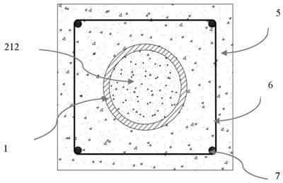
[0761] Embodiment 1.——I type section ( Figure 5 and Figure 6 )

[0762] Steel pipe cement mortar composite structure, at a certain stage in the production process such as Figure 5 and Figure 6 shown. Part A is composed of a steel pipe 11 , a lower blocking plate 12 and an upper blocking plate 13 . A threaded circular hole 121 is provided at the center of the lower blocking plate 12 , and a threaded circular hole is also provided at the center of the upper blocking plate 13 , and a construction pipe 51 is connected to the hole. After the construction is completed, the construction pipe 51 will be unloaded or sawn off.

[0763] The steel pipe 11 of part A adopts Q420 steel, and when the wall thickness is less than or equal to 16mm, its design value of tensile strength is 380MPa. When the temperature does not exceed 300°C, the strength of the steel does not decrease; when the temperature is 374°C, the design strength is 363MPa. The steel pipe 11 is a seamless steel pip...

Embodiment 2

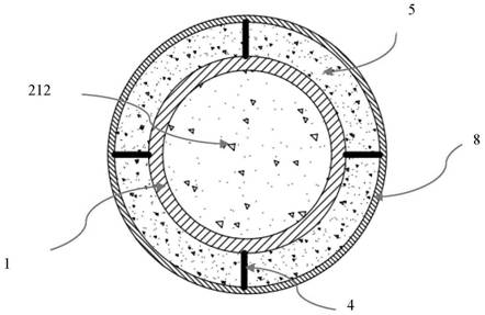
[0801] Embodiment 2.——II type section ( Figure 7 , Figure 8 )

[0802] Nearly completed CFST composite structures such as Figure 7 and Figure 8 shown. Part A of this structure is made up of steel pipe 11 , lower sealing plate 12 and upper sealing plate 13 . There is a feed circular hole 131 at the eccentric position of the upper blocking plate 13, which is used to inject B1 material; at the center of the upper blocking plate, a piston hole is arranged, and a pressurizing piston 6 is inserted in the hole, and the surface of the pressurizing piston Smooth, with a sealing ring set between the piston and the hole wall. There is an isolation device 3 inside the steel pipe. This device is an iron pipe with round holes distributed on the surface. The diameter of the round holes is 5-7mm. The outside of the iron pipe is wrapped with a metal mesh. The mesh is square and the eye width can be between 0.5-2mm. choose between. The iron pipe used as the isolation device is fixed ...

Embodiment 3

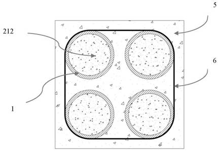
[0807] Embodiment 3.——II type section ( Figure 9 , Figure 10 )

[0808] Concrete-filled steel tube composite structures such as Figure 9 and Figure 10 As shown, part A is composed of a steel pipe 11 , a lower sealing plate 12 and an upper sealing plate 13 . The cavity of part A is provided with an isolating device, which is made up of corrugated iron plates 31 and 32, and the corrugated plates are fixed on the inner wall of the steel pipe. The surrounding area 22 of the corrugated plate is filled with material B2, the areas 211 and 212 between the steel pipe and the corrugated plate are filled with B1 material, and all the areas in the inner wall of part A that are in contact with the B1 material are coated with retarding antifriction material.

[0809] The maximum value that part A can withstand the fluid pressure in the cavity is 55MPa, and after B1 and B2 materials are filled into the cavity, a pressure of 50MPa is applied to it.

[0810] B1 material is reactive po...


PUM

PropertyMeasurementUnit
Wall thicknessaaaaaaaaaa
Tensile strengthaaaaaaaaaa
Outer diameteraaaaaaaaaa

Abstract

The invention discloses a manufacturing method of a multi-temperature maintenance combined structure, and the combined structure. The combined structure comprises a part A and a part B, wherein the part A is provided with a cavity, the part B is a solidifiable material filled in the cavity, is under the action of pressure in a solidification process, and comprises a part B1 and a part B2, the material B1 is a cement-based material, the material B2 is a solidifiable material, the material B2 has relatively high fluidity compared with the material B1, and the materials B1 and B2 in the cavity ofthe part A undergo a temperature and pressure process in the cavity. The invention discloses a combined column containing a single column and a latticed column containing the single column, wherein the single column is manufactured by adopting the manufacturing method of the multi-temperature maintenance combined structure.

Description

technical field [0001] The invention relates to the fields of buildings and bridges, in particular to a composite structure and a manufacturing method thereof. Background technique [0002] The concrete in the steel pipe concrete composite structure will shrink, which will cause separation between the concrete and the inner wall of the steel pipe, affecting the cooperative work between the two, and then affecting the mechanical properties of the composite structure. [0003] In the existing literature, there are two categories of methods to solve this problem. The first category is to change the shrinkage characteristics of the concrete material to reduce the shrinkage as much as possible, or to allow the material to expand. This type of method has nothing to do with the present invention, and will not be described in detail. [0004] The second type of method is to apply pressure to the concrete after it has been filled into the steel pipe. There are two methods for apply...

Claims


Application Information

Patent Timeline
IPC IPC(8): C04B40/02B28B11/24E04B1/30E04C3/36
CPCC04B40/0245C04B40/0263C04B40/0254B28B11/245E04B1/30E04C3/36C04B28/00
Inventor 王哲
Owner 王哲
Why Eureka
Try Eureka