Pipeline resistance increasing and pressure regulating control method

A pressure regulation control and pipeline technology, applied in the direction of diaphragm valve, valve device, valve housing structure, etc., can solve the problems of high difficulty in adjustment, easy fatigue of internal rubber hose, and failure of ball valve to work, so as to achieve good cut-off effect and alleviate fatigue defects , the effect of reducing the cross-sectional area

Active Publication Date: 2021-03-30
CHANGSHA RES INST OF MINING & METALLURGY
View PDF5 Cites 1 Cited by
  • Summary
  • Abstract
  • Description
  • Claims
  • Application Information

AI Technical Summary

Problems solved by technology

Due to the mass concentration of ore particles, general gate valves and ball valves cannot work under this condition
Although the pinch valve can operate in the slurry...

Method used


Image

  • Pipeline resistance increasing and pressure regulating control method
  • Pipeline resistance increasing and pressure regulating control method
  • Pipeline resistance increasing and pressure regulating control method

Examples


Embodiment Construction

[0037] The present invention will be further described in detail below in conjunction with the accompanying drawings and examples. The following examples are explanations of the present invention and the present invention is not limited to the following examples.

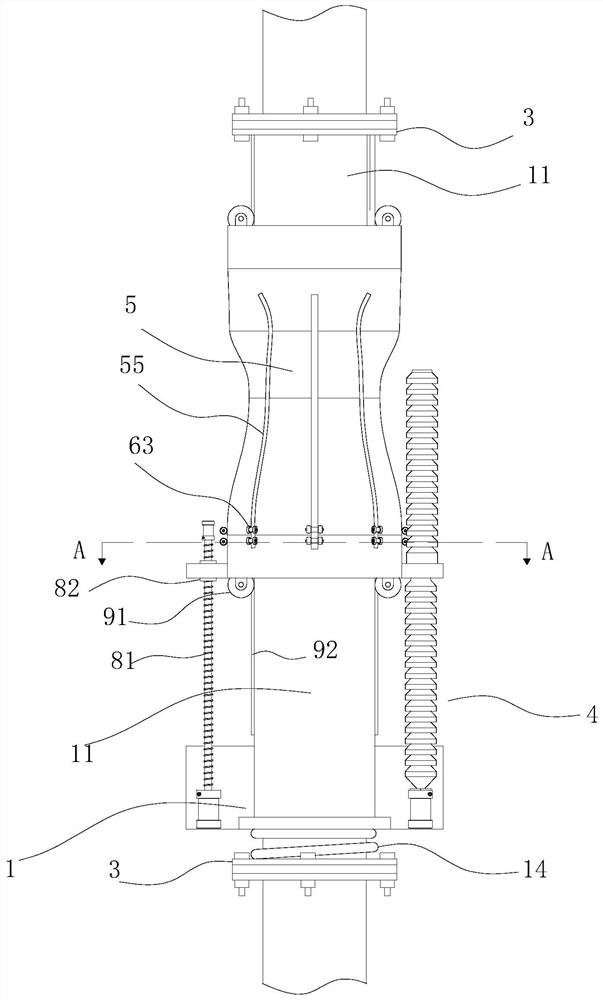
[0038] In this embodiment, a control method for increasing resistance and pressure regulation of a pipeline includes the following steps: step of boosting: eight briquetting blocks in the valve are simultaneously pressed on the outer wall of the rubber hose in the channel of the pipeline, and the briquetting blocks are under the action of external components, The pressing blocks move inward synchronously and equidistantly toward the radial direction of the rubber hose, and the eight pressing blocks exert eight radial pressures on the rubber hose area, and the cross section of the rubber hose shrinks under the action of the pressure; decompression steps: eight in the valve The briquetting block is pressed on the outer...


PUM


Abstract

The invention discloses a pipeline resistance increasing and pressure regulating control method. The method comprises the following steps that eight pressing blocks in a valve are pressed on the outerwall of a rubber pipe in a channel of a pipeline at the same time, under the action of an external part, the pressing blocks synchronously move towards the rubber pipe in the radial direction at equal intervals, the eight pressing blocks apply eight pressures towards the radial direction of the rubber pipe to a rubber pipe area, the section of the rubber pipe is changed under the action of pressure, so that the pipeline resistance is adjusted. In the process of reducing the cross section of a reducing valve, the cross section is approximately circular, and the deformation of the cross sectionof the rubber pipe is uniform, so that the fatigue defect can be relieved.

Description

technical field [0001] The invention relates to the field of valves, in particular to a control method for increasing resistance and regulating pressure of pipelines. Background technique [0002] In the pump slurry test system of the current mining transportation test system, the transported slurry is mixed with seawater and ore particles with a diameter of 3-30mm, and the mass concentration of the ore particles is between 3-15%. In the low-water deep-sea test mining transportation system, the slurry lift pump adopts deep-sea design parameters. In the 50m water deep-sea test, the pump outlet head may be 90-270m, far exceeding the demand for hydraulic transportation, so it is necessary to increase the transportation resistance in the pipeline and adjust The head flow rate of the pump makes it work in a reasonable power range. Due to the mass concentration of ore particles, general gate valves and ball valves cannot work under this condition. Although the pinch valve can op...

Claims


Application Information

Patent Timeline
IPC IPC(8): F16K7/06F16K27/02F16K31/44
CPCF16K7/06F16K27/0236F16K31/44
Inventor 郑皓关英杰胡琼李满红张明
Owner CHANGSHA RES INST OF MINING & METALLURGY
Why Eureka
Try Eureka