Carbon dioxide electrolytic device and method for electrolyzing carbon dioxide

A carbon dioxide and electrolysis device technology, applied in the electrolysis process, electrolysis components, electrolysis organic production, etc., can solve the problems of the deterioration of the output of the electrolysis cell, the increase of the voltage of the electrolysis cell, and the reduction of the CO generation amount.

Pending Publication Date: 2021-04-02
KK TOSHIBA
View PDF14 Cites 5 Cited by
  • Summary
  • Abstract
  • Description
  • Claims
  • Application Information

AI Technical Summary

Problems solved by technology

In using such an electrolytic cell, for example, by flowing a constant current in the cathode and anode, the CO 2 For example, in the reaction to generate CO, there is a problem that the output of the electrolytic cell decreases over time, such as a reduction in the amount of CO generated, or an increase in the voltage of the electrolytic cell.

Method used


Image

  • Carbon dioxide electrolytic device and method for electrolyzing carbon dioxide
  • Carbon dioxide electrolytic device and method for electrolyzing carbon dioxide
  • Carbon dioxide electrolytic device and method for electrolyzing carbon dioxide

Examples


no. 1 Embodiment approach

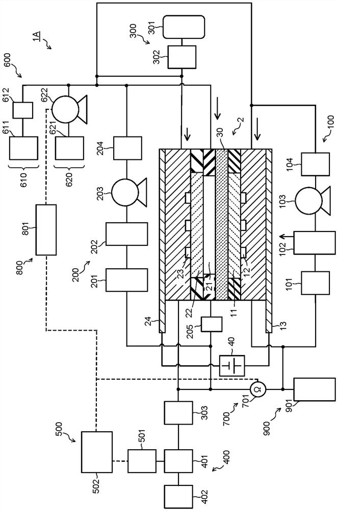
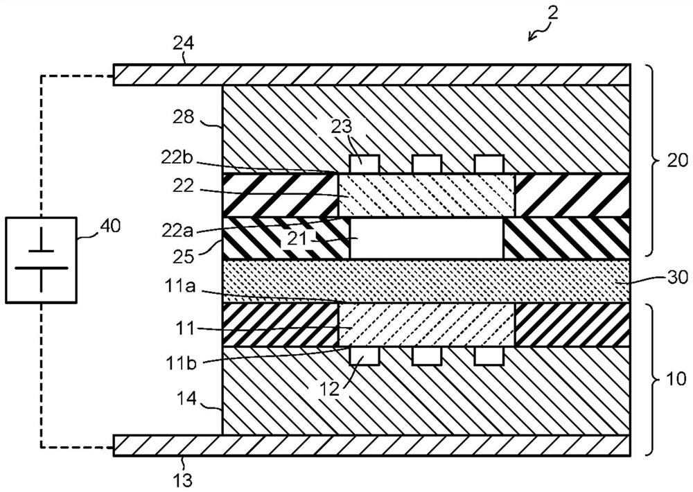
[0029] figure 1 It is a figure which shows the structure of the electrolysis apparatus 1 (1A) of the carbon dioxide of the 1st embodiment, figure 2 with image 3 is showing figure 1 A cross-sectional view showing the configuration of the electrolytic cell in the electrolytic device shown. figure 1 The illustrated carbon dioxide electrolysis device 1A includes: an electrolytic cell 2, an anolyte solution supply system 100 for supplying an anolyte solution to the electrolytic cell 2, a cathodic solution supply system 200 for supplying a cathodic solution to the electrolytic cell 2, and a system for supplying carbon dioxide gas to the electrolytic cell 2. The gas supply system 300, the product collection system 400 for collecting the product generated by the reduction reaction of the electrolytic cell 2, the electrolytic operation control system 500 for detecting the reducing performance from the collected product and controlling the electrolytic operation of the electrolytic ...

no. 2 Embodiment approach

[0064] Image 6 It is a figure which shows the structure of the electrolysis apparatus 1B of carbon dioxide of 2nd Embodiment. Image 6 The illustrated carbon dioxide electrolysis device 1B has a pipe for supplying the flushing liquid to the electrolytic cell 2 from the flow rate regulator (pump) 622 of the flushing liquid supply part 620 to the configuration of the carbon dioxide electrolysis device 1A of the first embodiment. The second conductivity meter 702 for measuring the conductivity of the flushing liquid before being introduced into the electrolytic cell 2 on the inflow port side of the flushing liquid supply line to the electrolytic cell 2 is basically the same as that of the carbon dioxide in the first embodiment. The electrolysis device 1A is the same. Like the first conductivity meter 701, the second conductivity meter 702 is electrically connected to the data collection and control unit 502 and the recovery operation control unit 801, and is controlled by the r...

no. 3 Embodiment approach

[0071] Figure 8 It is a figure which shows the structure of the electrolysis apparatus 1C of carbon dioxide of 3rd Embodiment. Figure 8 The carbon dioxide electrolysis device 1C shown in the second embodiment has an AC resistance meter 703 for measuring the impedance of the electrolytic cell 2 and an AC resistance meter 703 for measuring the impedance of the anode solution circulating in the anode solution supply system 100 are added to the configuration of the carbon dioxide electrolysis device 1B of the second embodiment. Electrolyte concentration measuring instrument 105 for electrolyte concentration, and measuring CO circulating in the electrolytic cell 2 2 The flow meter 304 for the flow rate of gas is basically the same as that of the carbon dioxide electrolysis device 1B of the second embodiment except for the configuration. The AC resistance meter 703 is the same as the first and second conductivity meters 701 and 702, and is electrically connected to the data colle...


PUM


Abstract

The invention relates to a carbon dioxide electrolytic device and a method for electrolyzing carbon dioxide. Provided is a carbon dioxide electrolysis device capable of efficiently operating an electrolytic cell while suppressing deterioration of the output of the electrolytic cell for a long period of time. The carbon dioxide electrolytic device (1) includes: an electrolysis cell (2) including acathode (22), an anode (11), a carbon dioxide supply flow path (23), solution supply flow paths (12,21), and a separator (30); a rinse solution source (620) which supplies a rinse solution to at leastone of the solution supply flow paths (12,21) and the carbon dioxide supply flow path (23); a first electric conductivity meter (701) provided on a discharge port side from the electrolysis cell of at least one of the solution supply flow paths (12,21) and the carbon dioxide supply flow path (23); and a rinse solution supply controller (801) which controls stop operation of the rinse solution source (620) according to a measurement result of the first electric conductivity meter (701).

Description

technical field [0001] Embodiments of the present invention relate to a carbon dioxide electrolysis device and a carbon dioxide electrolysis method. Background technique [0002] In recent years, it has been desired not only to utilize renewable energy but also to store and transport renewable energy from both viewpoints of energy issues and environmental issues. However, since the amount of power generated by renewable energy such as solar cells and wind power depends on weather and natural conditions, it is difficult to achieve a stable power supply. In such a case, an attempt has been made to store the generated electric power, but the cost of the storage battery and the loss during storage have become problems. [0003] Therefore, technologies that use renewable energy to electrochemically electrolyze water or convert carbon dioxide into chemical substances by electrochemical reduction have attracted much attention. According to such technology, it is also possible to ...

Claims


Application Information

Patent Timeline
Patent Type & Authority Applications(China)
IPC IPC(8): C25B15/08C25B1/23C25B3/26C25B9/19C25B3/07C25B3/03C25B15/023
CPCC25B15/08C25B1/00C25B1/04C25B9/73C25B3/25C25B9/19Y02E60/36Y02P20/133C25B15/02C25B15/023C25B15/083C25B15/029C25B15/025
Inventor 山际正和小野昭彦工藤由纪小藤勇介元茂朝日菅野义经北川良太御子柴智
Owner KK TOSHIBA
Why Eureka
Try Eureka