Bearing lubricating film thickness ultrasonic measurement method and system

A technology of ultrasonic measurement and bearing lubrication, applied in the direction of measuring devices, using ultrasonic/sonic/infrasonic, instruments, etc., can solve the problem of inability to effectively monitor the real-time and continuous changes of the bearing lubricating film thickness

Active Publication Date: 2021-04-02
HARBIN INST OF TECH
View PDF7 Cites 9 Cited by
  • Summary
  • Abstract
  • Description
  • Claims
  • Application Information

AI Technical Summary

Problems solved by technology

[0006] The purpose of the present invention is to solve the problem that the above method cannot effectively monitor the real-time continuous change of t

Method used


Image

  • Bearing lubricating film thickness ultrasonic measurement method and system
  • Bearing lubricating film thickness ultrasonic measurement method and system
  • Bearing lubricating film thickness ultrasonic measurement method and system

Examples


specific Embodiment approach 1

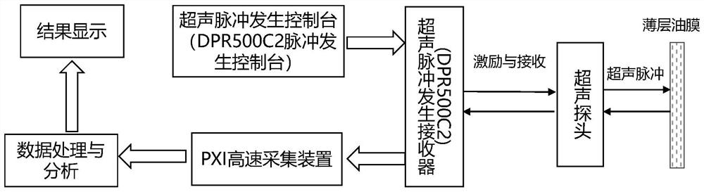
[0034] Specific implementation mode 1: The ultrasonic measurement method for bearing lubricating film thickness described in this implementation mode is specifically implemented through the following steps:

[0035] Step 1, using an ultrasonic probe to obtain an initial reference signal;

[0036] Step 2, when the bearing is running, obtain the ultrasonic reflection pulse signal of the lubricating oil film layer;

[0037] Step 3, performing fast Fourier transform on the reference signal collected in step 1 and the reflected pulse signal collected in step 2, respectively, to obtain the reflection coefficient of the lubricating film layer;

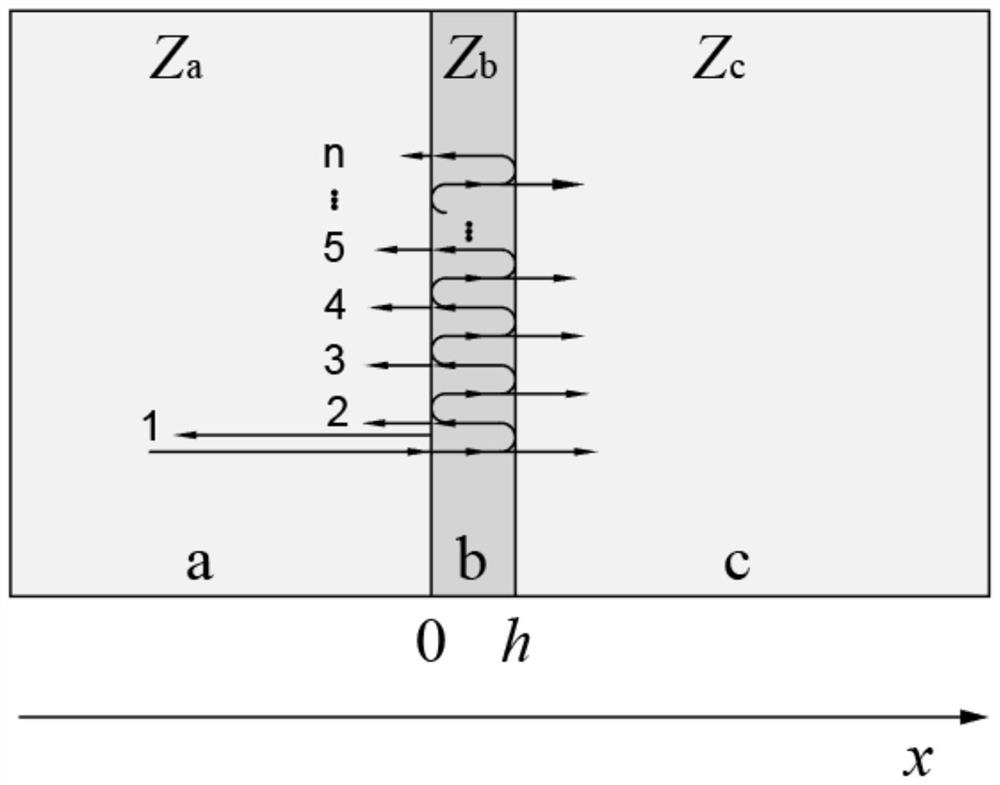
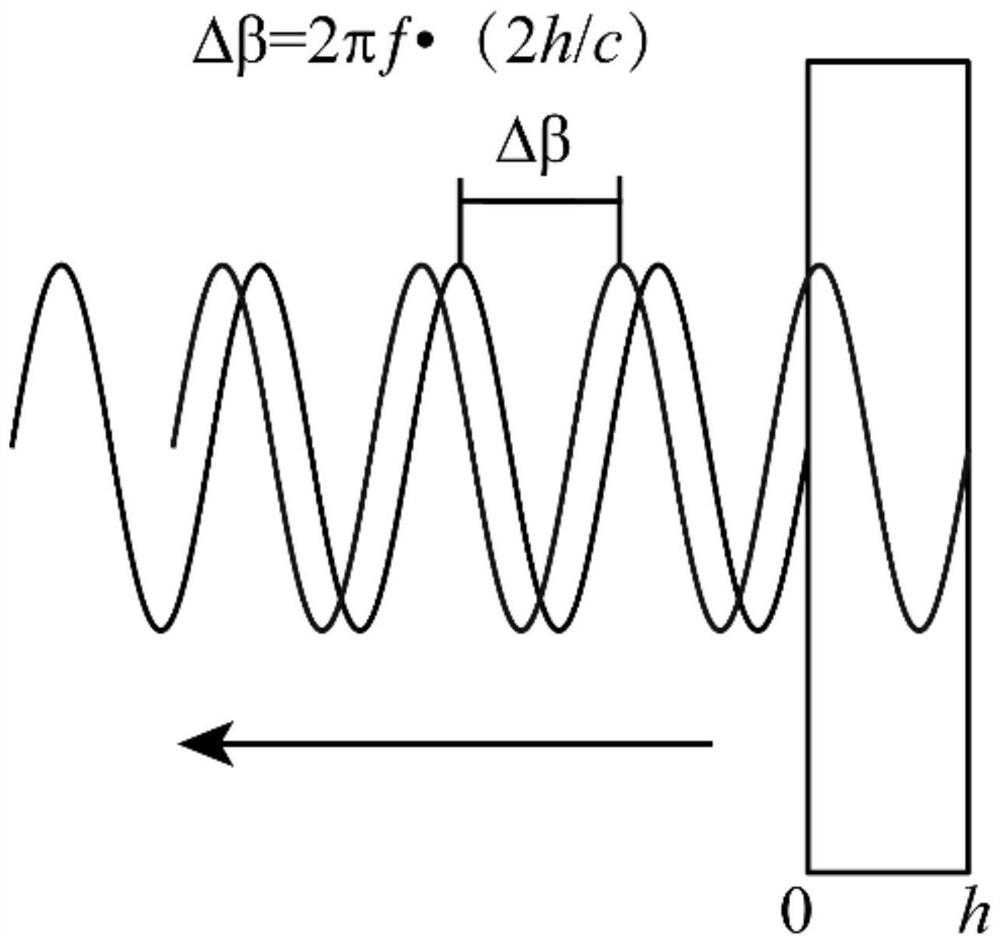
[0038] Step 4, using the lubricating film layer reflection coefficient obtained in step 3 to calculate the phase angle at which the latter reflected wave lags behind the previous reflected wave;

[0039] Step 5, based on the phase angle of the latter reflected wave calculated in step 4 lagging behind the previous reflected wave, the thicknes...

specific Embodiment approach 2

[0041] Specific implementation mode two: the difference between this implementation mode and specific implementation mode one is: the specific process of the step one is:

[0042] When the bearing has no lubricating film or the thickness of the lubricating film is greater than 300 μm, the ultrasonic probe is used to collect the reflected pulse wave of the reference interface, and the collected reflected pulse wave is used as the initial reference signal.

specific Embodiment approach 3

[0043] Specific implementation mode three: the difference between this implementation mode and specific implementation mode two is: the specific process of the step three is:

[0044] Fast Fourier transform is performed on the reflected pulse signal of the oil film layer to obtain the Fourier transform value A m , perform fast Fourier transform on the reference signal to obtain the Fourier transform value A ref ; Then the reflection coefficient of the oil film layer is obtained based on the following formula;

[0045]

[0046] Among them: R is the reflection coefficient of the lubricating film layer, R ref is the reference reflection coefficient.


PUM


Abstract

The invention discloses a bearing lubricating film thickness ultrasonic measurement method and system, belongs to the field of lubricating oil film thickness measurement and lubricating state monitoring, and solves the problem that the real-time continuous change of the thickness of the bearing lubricating film cannot be effectively monitored by using a single probe through a flight time method, aspring model method, a resonance model method and the like. According to the method, the oil film thickness is solved and obtained by establishing the quantitative relation between the lag phase angle and the reflection coefficient obtained through measurement and utilizing the linear relation between the lag phase angle and the oil film thickness. According to the method, a reflection coefficient obtained through measurement is converted into a lag phase angle, compared with a spring model, the oil film thickness measuring range of the single probe is improved to a large extent, continuous and accurate measurement of the oil film thickness from 0 micron to tens of microns can still be achieved under a high-frequency probe, and film thickness measurement in a wider range can be achieved in combination with a resonance model. The method can be applied to lubricating oil film thickness measurement.

Description

technical field [0001] The invention belongs to the field of lubricating oil film thickness measurement and lubrication state monitoring, and in particular relates to an ultrasonic measurement method and system for bearing lubricating film thickness. Background technique [0002] Bearings are an important part of gas turbines, water turbines, engines, etc., and are widely used in important areas of the national economy such as large-scale thermal power, hydropower, nuclear power, wind power, and large machine tools, as well as important areas related to national security such as military aircraft and ships. Speed, heavy load, high-precision working conditions. Under such working conditions, the failure of lubrication will cause serious wear and vibration of the radial sliding bearing, which will eventually lead to failure of the radial sliding bearing and damage to components, and even serious accidents. Therefore, it is necessary to monitor its lubrication status in real t...

Claims


Application Information

Patent Timeline
IPC IPC(8): G01B17/02
CPCG01B17/025
Inventor 汪剑云古乐张传伟李臻陆程赵小力郑德志王黎钦
Owner HARBIN INST OF TECH
Why Eureka
Try Eureka