Light beam drift compensation device without mechanical structure and implementation method thereof

A drift compensation, non-mechanical technology, applied in the field of optical communication and atmospheric optics, can solve the problems of demodulation failure, low response rate, short life, etc., achieve the effect of reducing algorithm complexity, no need for photoelectric conversion, and fast response time

Active Publication Date: 2021-04-02
NANKAI UNIV
View PDF6 Cites 0 Cited by
  • Summary
  • Abstract
  • Description
  • Claims
  • Application Information

AI Technical Summary

Problems solved by technology

[0007]The purpose of this invention is to solve the problems of low coupling efficiency, signal crosstalk, demodulation failure and other problems caused by beam drift in optical communication, and to break through the traditional mechanically driven beam drift compensation The solution has the bottleneck of low response rate and short life

Method used


Image

  • Light beam drift compensation device without mechanical structure and implementation method thereof
  • Light beam drift compensation device without mechanical structure and implementation method thereof
  • Light beam drift compensation device without mechanical structure and implementation method thereof

Examples


Embodiment 1

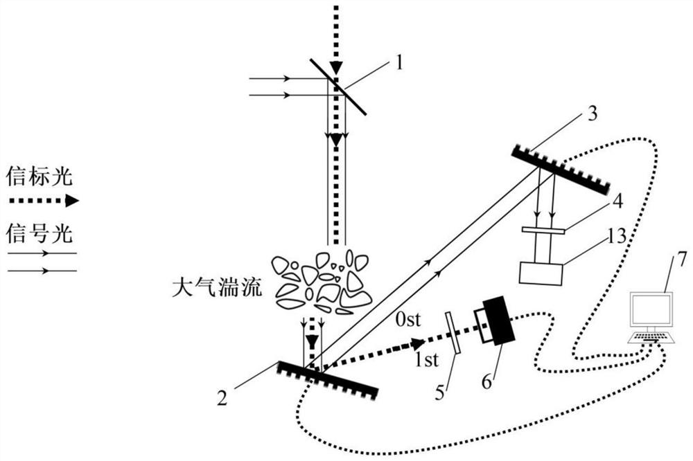
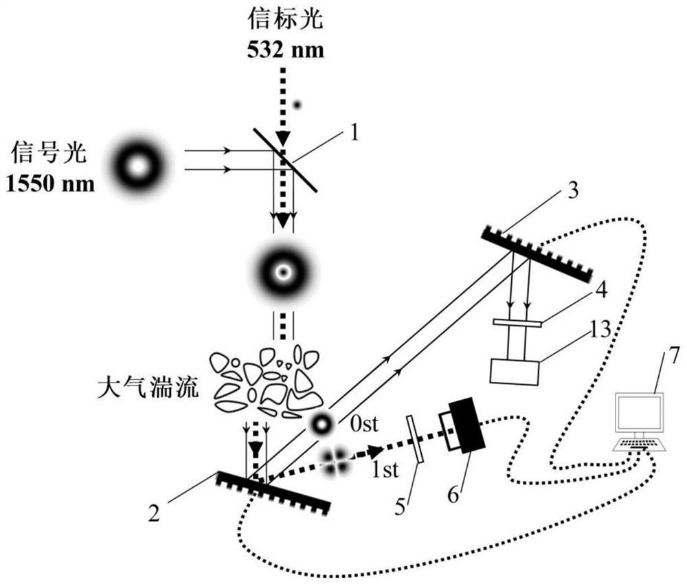
[0061] refer to image 3 As shown, it is a schematic diagram of Embodiment 1 of a beam drift compensation device without a mechanical structure. Based on the response of the spatial light modulator to different wavelengths, this embodiment provides a beam drift compensation device without a mechanical structure. The device comprises a dichroic mirror 1, a first spatial light modulator 2, a phase hologram 201, a blazed grating hologram 202, a second spatial light modulator 3, a first optical filter 4, a second optical filter 5, CCD camera 6 , computer 7 and signal receiving unit 13 . Wherein, the first spatial light modulator 2 and the second spatial light modulator 3 are placed in parallel.

[0062] The dichroic mirror 1 is used to coaxially combine the signal light and the beacon light, and the first spatial light modulator 2 is loaded with a phase hologram 201 and a blazed grating hologram 202 for modulating the beacon light and combining the beacon light Light and signal ...

Embodiment 2

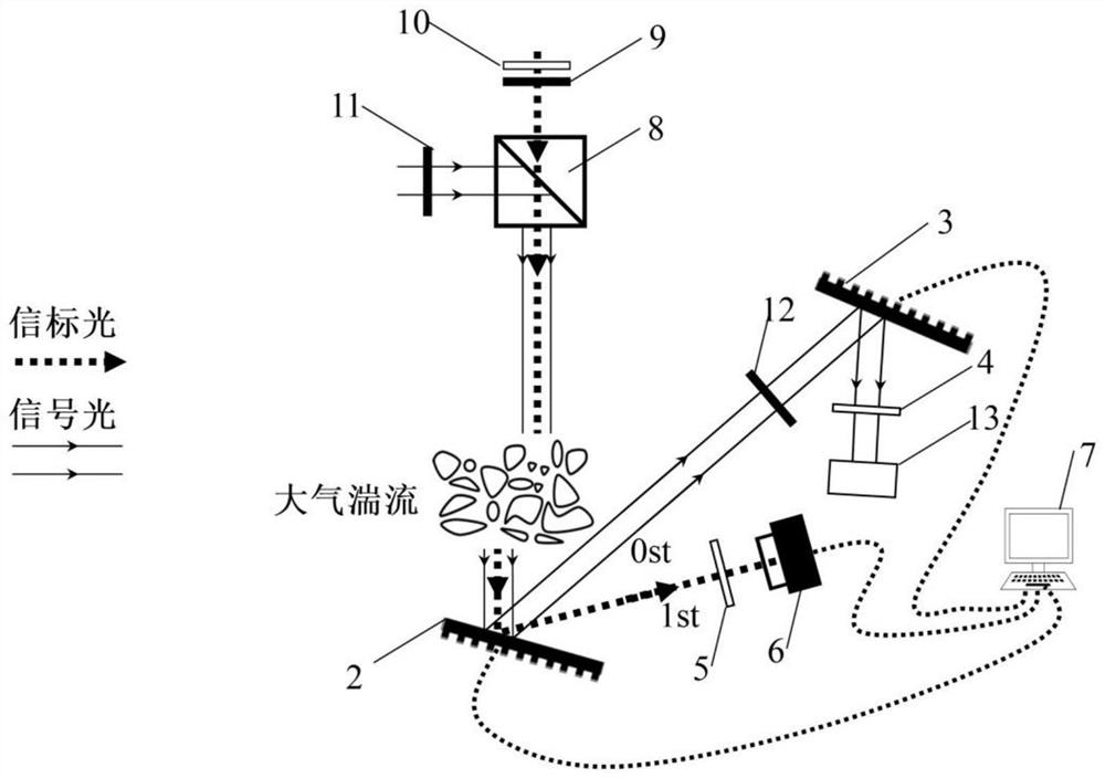
[0074] refer to Figure 7 Shown is a schematic diagram of Embodiment 2 of a beam drift compensation device without a mechanical structure. The difference between this device and the first embodiment is that the second embodiment is based on the response of the spatial light modulator to different polarization states to realize the spatial separation of the beacon light and the signal light, so it is necessary to change the dichroic mirror 1 in the first embodiment to Beam combiner 8, and add optical elements for adjusting the polarization state of incident signal light and beacon light: polarizer 10, first half-wave plate 9, second half-wave plate 11, third half-wave plate 12. The polarizer 10 and the first half-wave plate 9 are placed in parallel, the beacon light enters the beam combiner 8 through the polarizer 10 and the first half-wave plate 9, the signal light enters the beam combiner 8 through the second half-wave plate 11, and the third The half-wave plate 12 is arrang...


PUM


Abstract

The invention discloses a light beam drift compensation device without a mechanical structure and an implementation method thereof, and the method achieves the light beam drift compensation through the sensing of probe structure light, a programmable phase hologram and the modulation of wavelength-dependent and polarization-dependent liquid crystal light. The device comprises a dichroscope, a beamcombiner, a spatial light modulator, a CCD camera, a computer and the like. The beam combiner / dichroscope is used for coaxially combining signal light and beacon light, the first spatial light modulator is used for only modulating the beacon light to generate petal-shaped probe structured light distributed in the angular direction, and the petal-shaped probe structured light is recorded by the CCD camera to realize drift amount vector perception and send the drift amount vector perception to the computer; and the computer synchronously controls the relative positions of the phase holograms ofthe first spatial light modulator and the second spatial light modulator and the blazed grating period to realize light beam drift compensation. A mechanical displacement driving device is not needed, the compensation precision is greatly improved, the response speed is greatly increased, the service life is greatly prolonged, and the method is a reliable scheme for free space optical communication beam drift compensation.

Description

technical field [0001] The invention belongs to the fields of optical communication and atmospheric optics, and in particular relates to a beam drift compensation device without a mechanical structure and a realization method thereof. Background technique [0002] Atmospheric turbulence can cause attenuation (scattering, absorption, spatial attenuation, etc.) and refractive index disturbances (random phase disturbances, beam drift, etc.) on the beam transmitted by the channel. The beam drift is manifested in that the center of the signal beam cannot be aligned with the receiving detector at all times, resulting in low coupling efficiency and receiving power jitter. [0003] The traditional solution to the problem of beam drift relies on the APT (Aiming, Acquisition and Tracking) system. The principle is: after the beam position is obtained by the QD (Quadrant Detector), it is driven by a device that generates mechanical displacement (pan / tilt, micro-electromechanical system,...

Claims


Application Information

Patent Timeline
Patent Type & Authority Applications(China)
IPC IPC(8): G02B27/09
CPCG02B27/0944G02B27/0905G02B27/0988
Inventor 刘波常琨李昌瑾刘海锋刘艳格王志张昊闫宝罗
Owner NANKAI UNIV
Why Eureka
Try Eureka